Advanced Sheet Metal Design Using NX Cad Challenge_2_Box Assembly
BOX ASSEMBLY :
MAIN OBJECTIVE :
To write a detailed report on Sheet Metal Component with good explanation on Sheet Metal modelling tools applied throughout the modelling of Sheet Metal Box Assembly.
INTRODUCTION :
To construct a sheet metal box assembly using NX CAD tools and operations to construct step by step of sheet metal process into the final component. It consists of.
- The steps I have followed in NX CAD.
- The tools I've used.
- The operations I've done to acquire the final component.
PROCEDURE :
- After creating the part file I've drawn a sketch of a Rectangle with given Dimesions and used TAB command to make it into a Thicken component of 1 MM.
- I've used flange command to the side of the tab of length 200 MM with Bend Radius of 10 mm.
- Then from the side edges of the flanges on the one side I've drawn two flanges of 70 MM length and I've used CLOSED CORNER command to fill the gap between the flanges and the base.
- HEM FLANGE command was used to connect the two edges of the flanges.
- After completing the One side of the box I've mirrored it to the other side using the ZY plane as the refernces and used UNITE command to unite the mirror part with the main body and made it inti the whole part.
- I've used DIMPLE in sketch feature to draw an HORIZONTAL X like shape on the side of the box and provide DIMPLE using DIMPLE command.
- I've mirrored those DIMPLE usin the MIRROR FEATURE command using ZX plane to the other side.
- Then I've drawn rectangular cutout at the bottom of the box and used DIMPLE command to provide a dimple on the base.
- I've used UNBEND to have a look at the component.
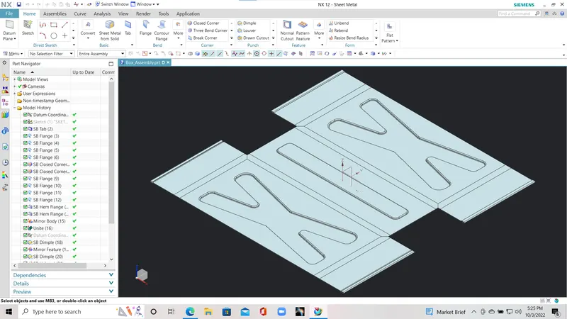
- Then I've used BEAD command and in sketch feature to provide 4 Circular beads at the bottom of the base used the MIRROR FEATURE command again here.
- Then I've used REBEND command to complete the design and Provided flanges to the edges of the top of the box on all four sides excepts the corner. And I've used the exact top side sketch to provide a tb on top to cover the box or lid using the sketch and having the datum plane of XY plane offset upto 203 MM.
- After completion of the box I've drwan a rectangle cutout at the side od the box and provided BREAK CORNER and then provide Flanges and HEM flanges to the required and get an output as design suggested. After that I've unbend the FLANGES and provided cutouts as suggested in the given data
- Then I've mirrored the flanges using MIRROR BODY command to the other side of the HEM using the ZX plane.
- I've done the sam above steps to get the desired output on the top of the the led And mase it into a final component.
- I've used drafting to provide the neccassary views on the drafting sheet.
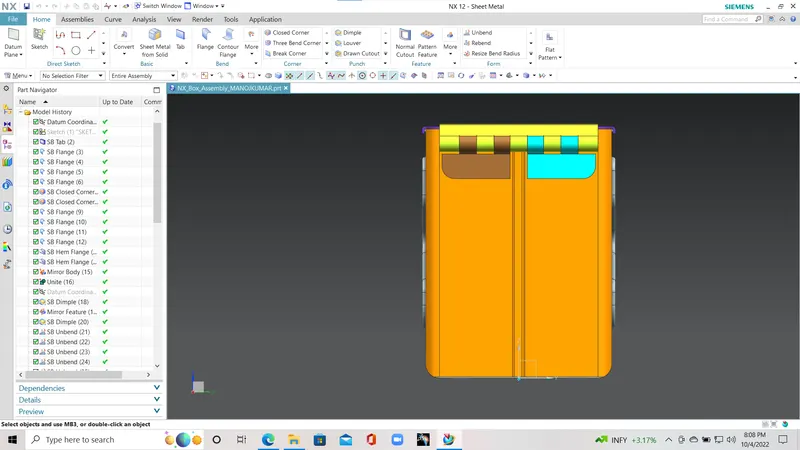
BOX ASSEMBLY VIEWS :
ISOMETRIC VIEW :
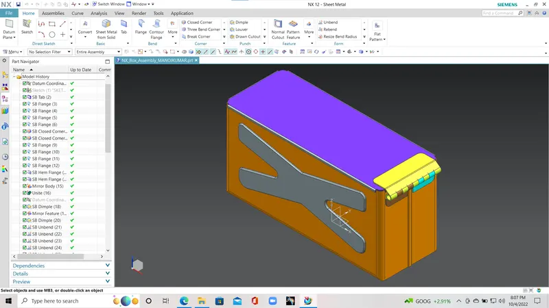
TOP VIEW :
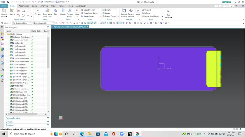
FRONT VIEW :
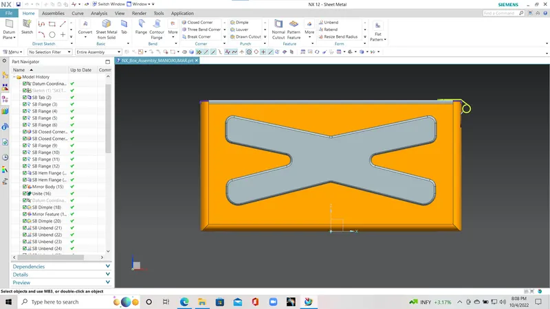
SIDE VIEW :
CONCLUSION :
I've followed the guidelines and the commands given in the data provided to make a complete component of the sheet metal BOX assembly design.