Advanced Sheet Metal Design Using NX Cad Challenge_2_Box Assembly
* Title : Report on Sheet metal component .
* Objective : To Design a sheet metal Component with good explanation on Sheet Metal modelling tools applied throughout the modelling. And to attach the images as required .
* Introduction : Open NX and create a rectangular sketch ,genearate a solid model use tab .Moreover Perform Flanges ,hem,normal cutout and hole if required .
* Design Methodology :
| Open NX and start with new file . |
| Sketch the model with given dimensions and applying thickness . |
| Peroming of tab ,flanges cutout ,hems and holes. |
| Saving the model and exit . |
* Description :
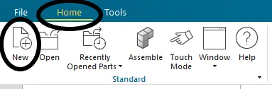
* Open the Nx and start with new file .
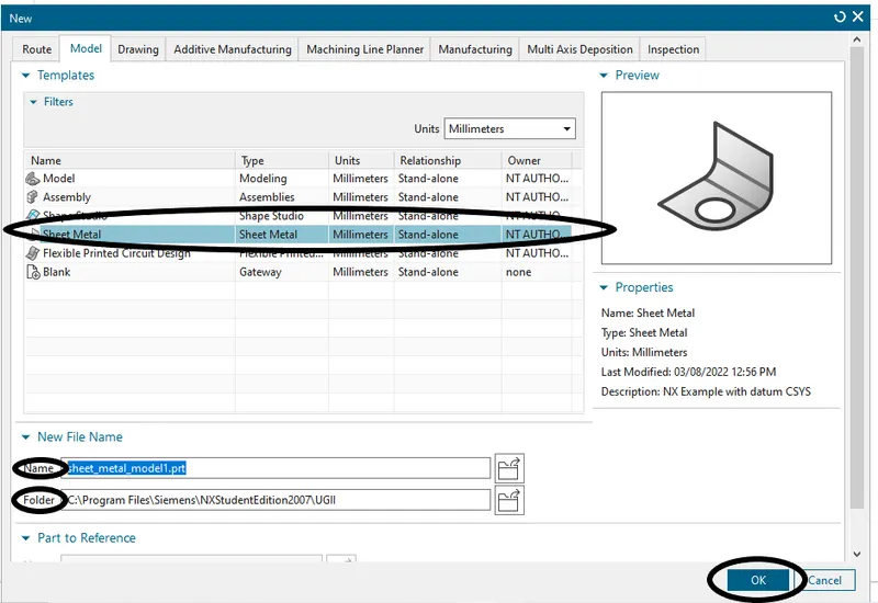
* Click new from toool bar and select the type as sheet metal model .
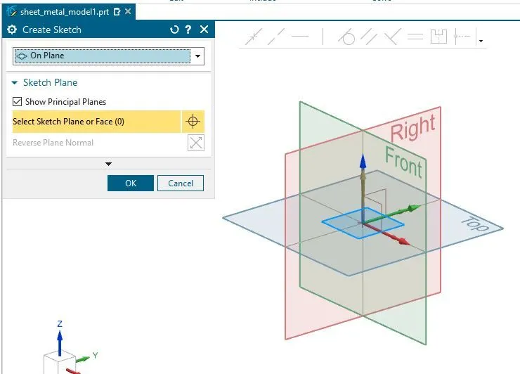
* Select a XY-Plane which need to be performed on a plane and click ok as shown below:
* Sketch a Model :
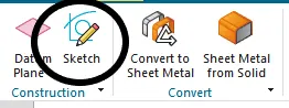
*After opening the NX ,from tool bar select sketch a rectangle and desing the sketch as required .
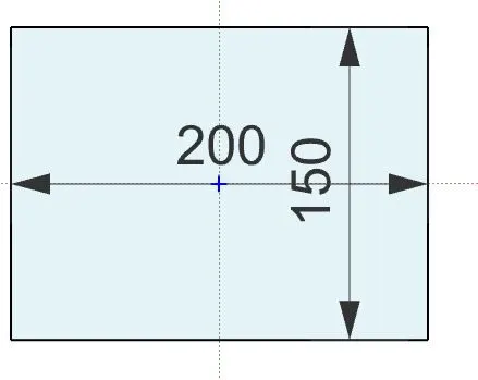
* The diemsion for rectangle are 200mm and 120mm as hown below :

* Image :
*Performing of Tab Tool :
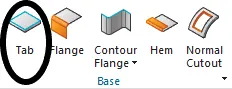
* Tab : The process that Creates a bas feature by extruding a sketch along a vector by a thickness value.
* Sketching a rectangle :
* After Opening the Nx with new file click to sketch from tool bar and draw a rectangle of 200 mm and 150mm and click finish as shown in below encircled .
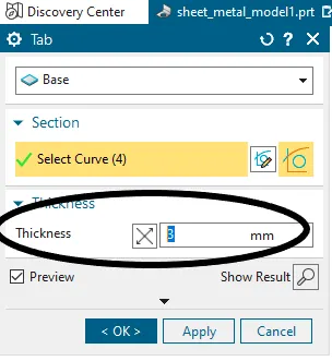
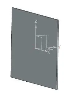
* Now,select tab from tool bar and select the edge of sketch ,click ok .
*Give the thickness as 3mm for tab as shown below:
* Performing of Flange :
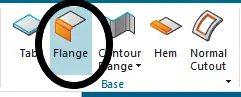
Flange : This Process adds a flat flange at an angle to a planar face and adds a bend between the two.
*After completing the tab tool ,click to flange and select the required edge which need to be flange.
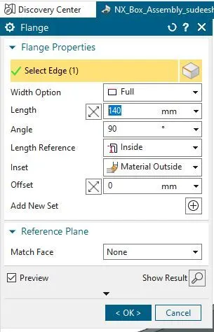
*As performing the Flange given the width option as full as this selects the complete edge as it is sketched .
* Now,the angle 90 ,and the length reference to inside ,inset from outside as the flange starts from the selected edge.
* Giving the length as 140mm in flange and click ok as shown below.
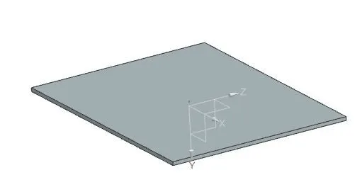
* Before Performing Flange :
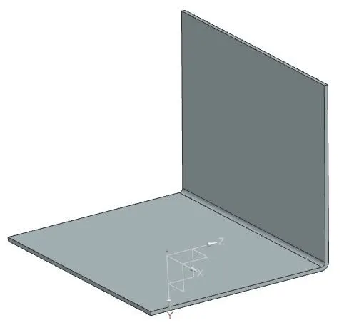
* After Performing Flange :
* Performing of Flange in opposite side :
*Again select the flange and select the required edge which need to be flange.
*As performing the Flange given the width option as full as this selects the complete edge as it is sketched .
* Now,the angle 90 ,and the length reference to inside ,inset from Material outside as the flange starts from the selected edge.
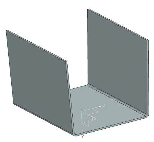
* Giving the length as 140mm in flange ,giving angle as 90 and click ok as shown below.
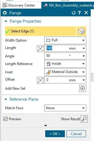
* Before Performing Flange :
* After Performing Flange :
* Performing of Flange in other side :
*Moreover, select the flange and select the required edge which need to be flange.
*As performing the Flange given the width option as full as this selects the complete edge as it is sketched .
* Now,the angle 90 ,and the length reference to inside ,inset from Material outside as the flange starts from the selected edge.
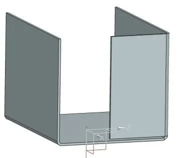
* Giving the length as 70mm in flange ,giving angle as 90 and click ok as shown below.
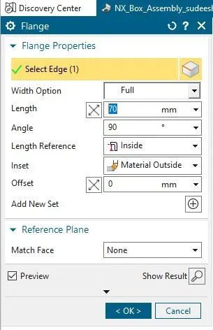
* Before Performing Flange :
* After Performing Flange :
* Performing of Flange in other side :
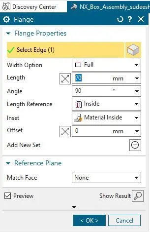
*Again select the flange and select the required edge which need to be flange.
*As performing the Flange given the width option as full as this selects the complete edge as it is sketched .
* Now,the angle 90 ,and the length reference to inside ,inset from inside as theflange starts from the selected edge.
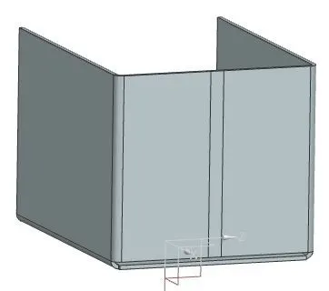
* Giving the length as 70mm in flange and click ok as shown below.
* Before Performing Flange :
* After Performing Flange :
* Performing of Corner :
Corner : It is a tool tab that is used for closing the two surface as required .
* This performing of closed surface can be done one by one .
*Performing the closed surface 1.
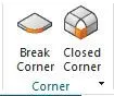
* From Corner tool select closed corner .
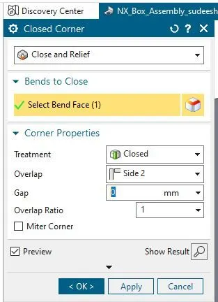
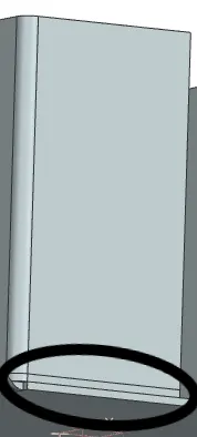
*Now ,select the surface which need to be closed and also select the surface accordingly to close both the surface as shown below .
* In closed corner ,keeping the treatment as closed and using the overlap to silde 1 open that closes the surface as one after the other and not intersecting .
* Before performing the closed surface :
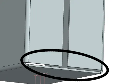
*After performing the closed surface :
*Performing the closed surface 2.
* From Corner tool select closed corner .
*Now ,select the surface which need to be closed and also select the surface accordingly to close both the surface as shown below .
* In closed corner ,keeping the treatment as closed and using the overlap to silde 2 open that closes the surface as one after the other and not intersecting .
* Before performing the closed surface :
*After performing the closed surface :
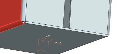
* Performing of Flange Before performing of HEM :
* Select the flange and select the required edge which need to be flange.
*As performing the Flange given the width option as full as this selects the complete edge as it is sketched .
* Giving the length as 6.5mm at angle 90
* Now,the angle 90 ,and the length reference to inside ,inset as bend outside starts from the selected edge.
* Give the bend radius 0.5mm Neutral factor as 0.3330 click apply as shown below.
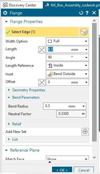
* Before performing of flange with bend radius :
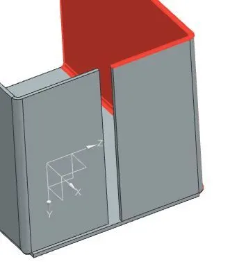
* After performing of flange with bend radius :
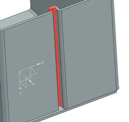
Performing of Flange Before performing of HEM :
* Select the flange and select the required edge which need to be flange.
*As performing the Flange given the width option as full as this selects the complete edge as it is sketched .
* Giving the length as 6.5mm at angle 90
* Now,the angle 90 ,and the length reference to inside ,inset as bend outside starts from the selected edge.
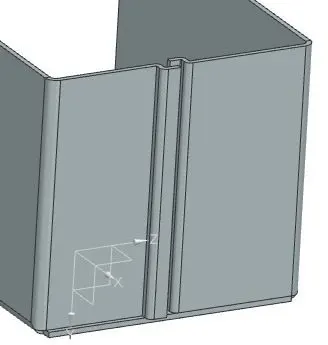
* Give the bend radius 0.5mm Neutral factor as 0.3330 click apply as shown below.
* Before performing of flange with bend radius :
* After performing of flange with bend radius :
*Performing of HEM tool :
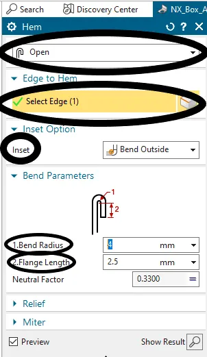
HEM : This process folds the edges of sheet metal flange over onto itself for the purpose of self handling with certain radius .hems folds the flat surface completly i,e a hook type.
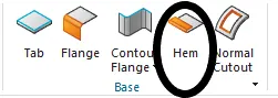
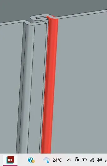
*After completing the tab tool ,from base click to hem and select the required edge which need to be flange.
* Change the hem to open ,inset opton as bend outside .
* Now ,change the bending parameters as bend radius to 4 flange length 2.5mm and neutral factor as 0.3300 as shown below in encircled region .
* Before performing of Hem:
* After performing of Hem:
*Performing of HEM tool :
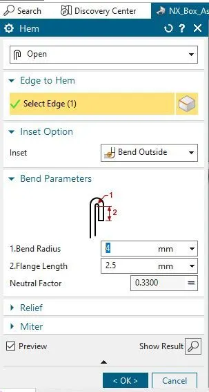
HEM : This process folds the edges of sheet metal flange over onto itself for the purpose of self handling with certain radius .hems folds the flat surface completly i,e a hook type.
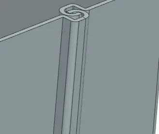
*After completing the tab tool ,from base click to hem and select the required edge which need to be flange.
* Change the hem to open ,inset opton as bend outside .
* Now ,change the bending parameters as bend radius to 4 flange length 2.5mm and neutral factor as 0.3300 as shown below in encircled region .
* Before performing of Hem:
* After performing of Hem:
* Mirroring the model :
Mirror body : The process that creates the extact body including the features ,by selecting the plane which is opposite of the plane which need to be mirror .
* From tool bar select mirror body and the body which need to be mirrored.
* select the plane which is of opposite to of mirroring body and click ok as shown below .
* The parent part need to be work part and click ok .
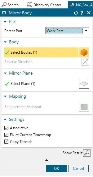
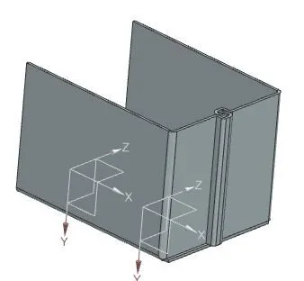
* Before performing of Mirror Body :
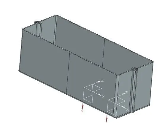
* After performing of Mirror Body:
* Performing of unite option:
Unite : The process that merges the two different body to one body.
* From tool bar select the unite option and select the bodies which need to merged to one .
*keep the tolerence 0.01 as shown below.
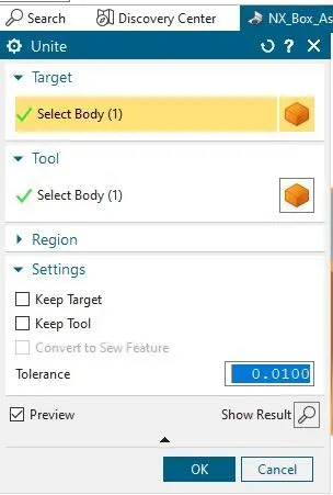
* Before performing of Unite :
* After performing of Unite :
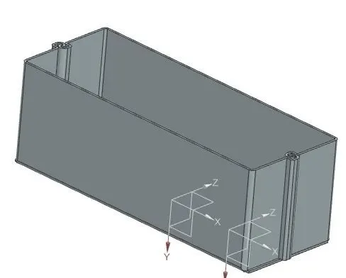
* Dimple : It is a process that Lifts an area of model insides a sketch that stimulates a stamping tool with required depth.
*Sketching the surface :
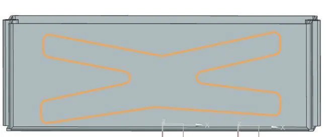
* Before performing dimple sketch need ti be done .
*Select the surface where the sketch has to be done and draw a sketch.
* Perform a fillet a with radius 8mm as shown below.

* Model Before performing sketch :
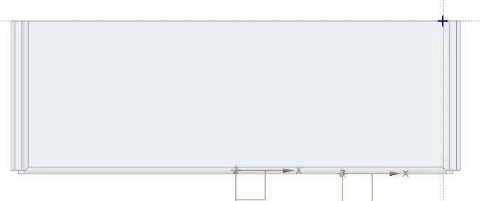
* Model After performing sketch :
* Performing of dimple :
* Select dimple from tool bar and select the sketch which need to be dimple .
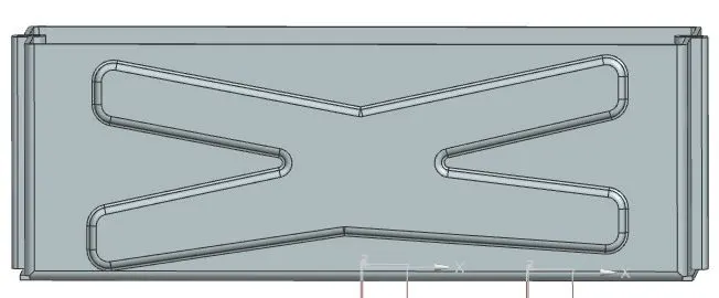
*The select surafce gets lifts to certain depth as show below.
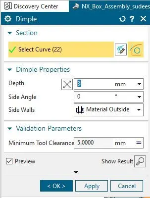
* Model Before performing Dimple :
* Model After performing Dimple :
* Mirroring the model :
Mirror body : The process that creates the extact body including the features ,by selecting the plane which is opposite of the plane which need to be mirror .
* From tool bar select mirror body and the body which need to be mirrored.
* select the plane which is of opposite to of mirroring body and click ok as shown below .
* The parent part need to be work part and click ok .
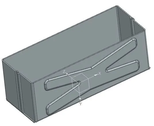
* Before performing of Mirror Body :
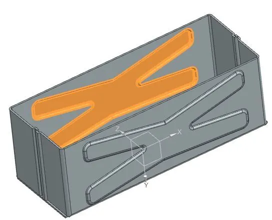
* After performing of Mirror Body:
* Dimple :
It is a process that Lifts an area of model insides a sketch that stimulates a stamping tool with required depth.
*Sketching the surface :
* Before performing dimple sketch need ti be done .
*Select the surface where the sketch has to be done and draw a sketch.
* Perform a fillet a with radius 8mm as shown below.
* Model Before performing sketch :
* After performing sketch :
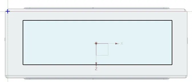
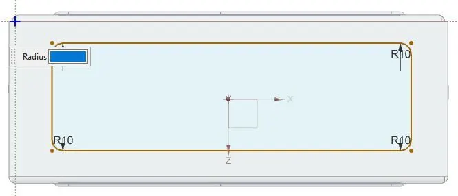
* Performing fillet for above rectangle sketch :
* From Curve tool bar select fillet and select the sketches .
* Now, by selecting the selecting the sketches give the radius to 10mm as shown below .

* Before performing Fillet :
*After performing Fillet :
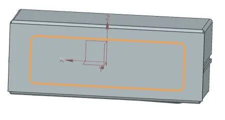
* Before performing Dimple :
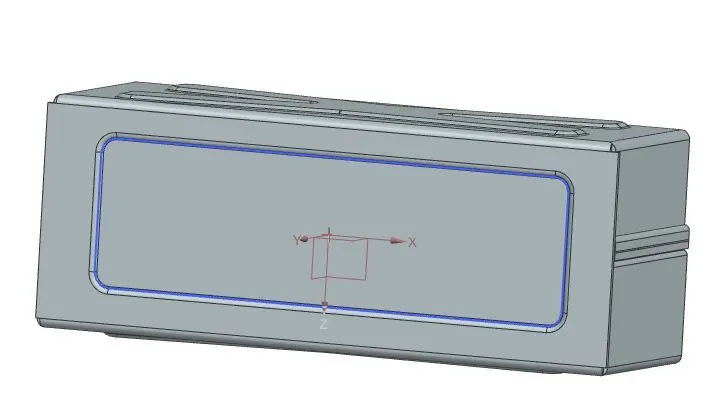
* After performing Dimple :
* select dimple from tool bar and select the edges which neeed to be lifted .
*Give the radius to 2mm lift as shown below .
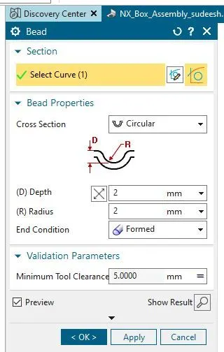
* Performing of Bead option :
*Bead : This is function the creates a circular cross section area with certain depth and radius .
* From to bar select bead option and selec the curve which need to be bead .
* In bead properties ,select the cross section to circular and giving the depth to 2mm and the radius to 2mm.
*Now,Select the end condition to formed and give minimum tool clearance to 5mm and click ok as shown below .
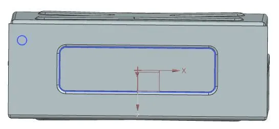
* Before performing Bead :
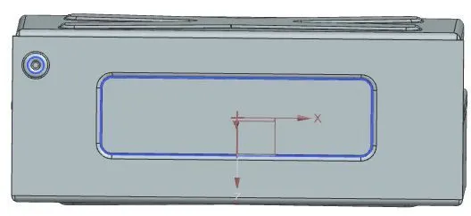
* After performing Bead :
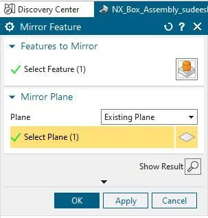
* Mirroring of performed bead :
* As mirror option is already performed in for before features ,select mirror features from tool bar.
* Select the bead feature and sketch which to be mirror .
*Moreover ,select plane to which the mirrored feature need to be placed and click apply as shown below .
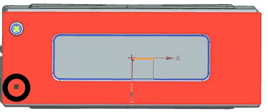
* Bead before Performing Mirror feature :
* The encircled region shown point created by mirror feature and click ok
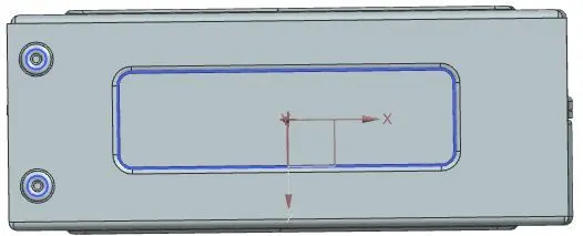
* Bead After Performing Mirror feature :
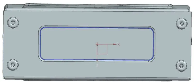
* Again performing of bead as mention above :
* Performing the model with Unbend option:
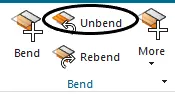
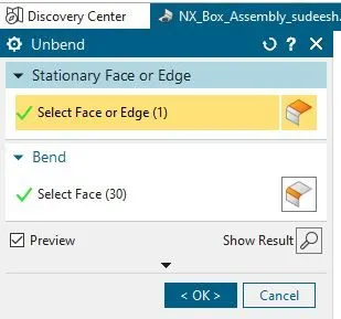
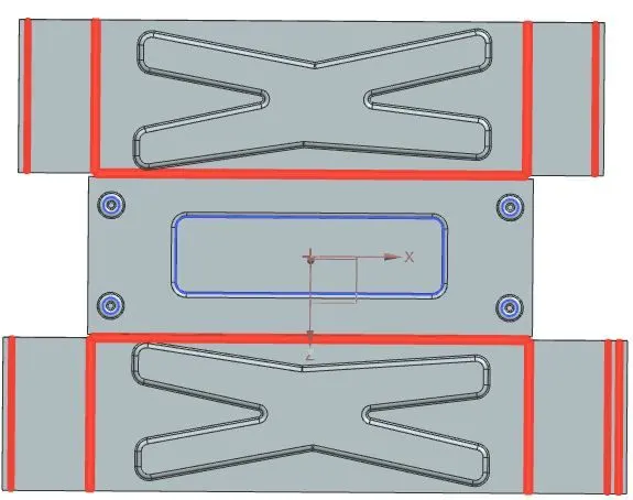
UnBend : The process that flatters thesurface with respect to selected surface .
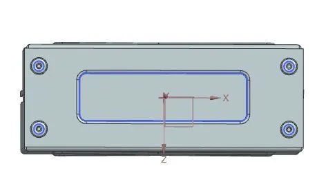
* Select the unbend from bend tool bar and select a surface as required to make a flat surface ,a ideal surface .
* Furthermore ,click ok to continue the process as shown below .
* Model before using unbend :
* Model After using unbend :
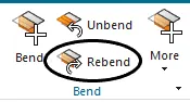
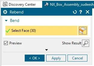
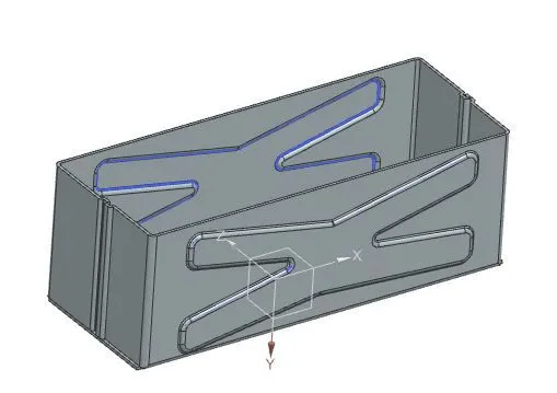
* Performing of Rebend :
Rebend: This function restores an unbend feature to its orevious bent state ,along with any features added after the unbend feature .
* Now, from Bend tool bar select the rebend and Drag the surface which are required as shown below;
* Model before using Rebend :
* Model After using Rebend :
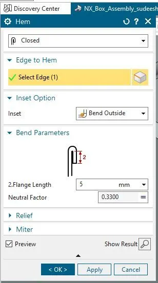
* Performing of hem :
HEM : This process folds the edges of sheet metal flange over onto itself for the purpose of self handling with certain radius .hems folds the flat surface completly i,e a hook type.
*After completing the tab tool ,from base click to hem and select the required edge which need to be flange.
* Change the hem to Closed ,inset opton as bend outside .
* Now ,click ok as shown below ;
* Model before using Hem :
* Model After using Hem :
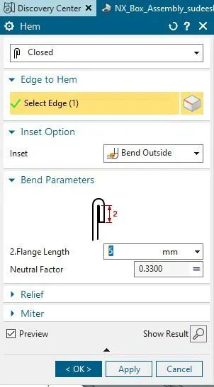
* Performing of hem for other sides :
* Select the other edge and edit the changes as mention above
* and click ok .
* Model before using Hem :
* Model After using Hem :
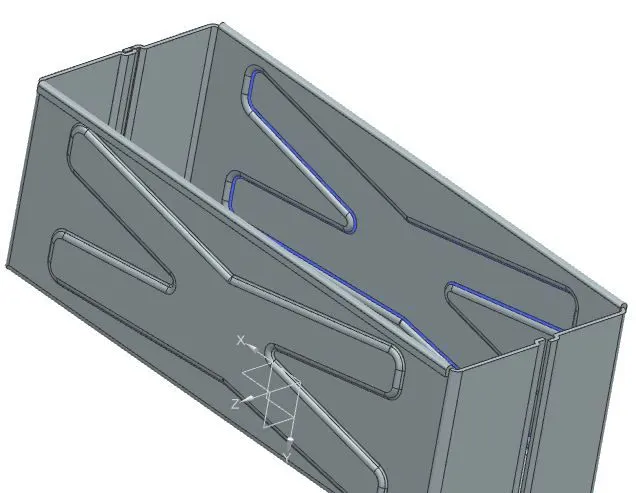
* Model After using Hem :
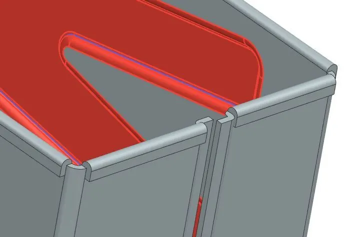
* Complete Model After using Hem :
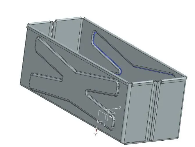
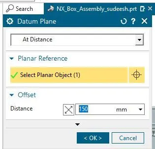
* Performing of datum Plane :
*Datum Plane : It is a plane that created when requires for creating new sketches and features.
* From construction tool bar select datum plane .
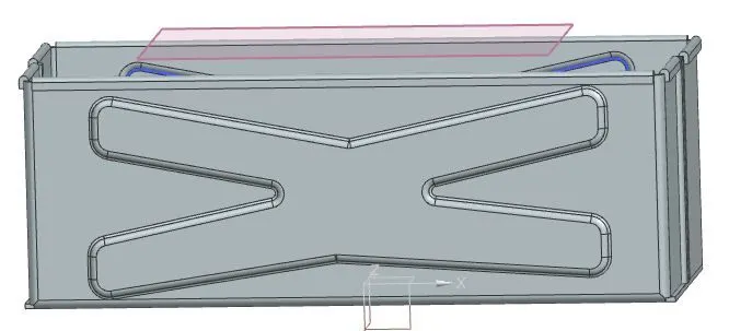
*Select the plane and give a distance to 150mm as required and click ok as shown below :
* Before creating Datum plane:
*After creating Datum plane:
* Skecting and Performing of Tab :
Tab : The process that Creates a bas feature by extruding a sketch along a vector by a thickness value.
* Sketching :
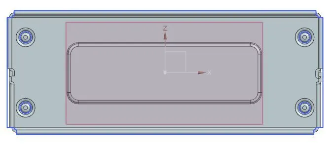
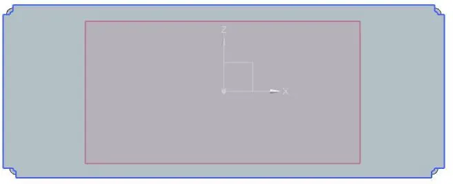
* Creating a top surface which the box needs to be closed.
* Select sketch and start with line ,draw a line accordinly .
* After drawing ,select the Arc and connect the lines as shown below ;
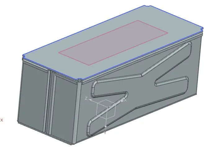
* The blue line shows the sketch created .

* Before Performing Tab :
* After Performing the tab :
* Performing of Lock to Top surface and lower box :
* Select the surface and click to sketch .
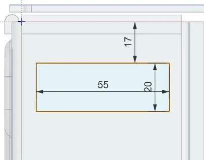
* Futhermore,draw a rectangle of 20mm length and a width of 55mm.
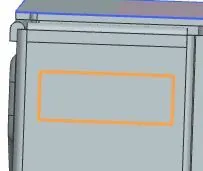
* After completion of sketch click to finish as show below ;
* Before performing sketch :
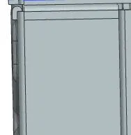
* After performing sketch :
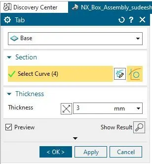
* Performing of Tab :
* After sketching ,from base tool bar select tab tool bar.
* Change the selection option from secondary selection to base .
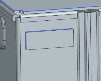
* select the sketch requied for tab and give the thickness 1mm as shown below ;
* Sketch before performing tab option:
* Sketch After performing tab option:
* Performing of Break Corner :
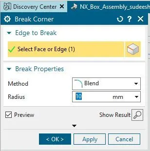
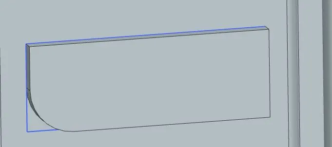
Break Corner : It is process that Converts the sharp edges to circular edges with required radius .
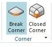
*Now ,from corner tool select break corner and select the edge .
* After selecting the edge give radius 10mm as shown below .
* Before performing break corner :
* After performing break corner :
* Performing of Flange :
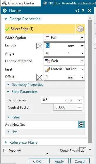
* Click to flange from base tool .
* Select the edge of surface which are done by tab .
* Give the width option to full length as 10mm and angle 40 .
* selecting the required length reference and Inset ,click apply as shown below
* Before Performing of Flange
* Before Performing of Flange
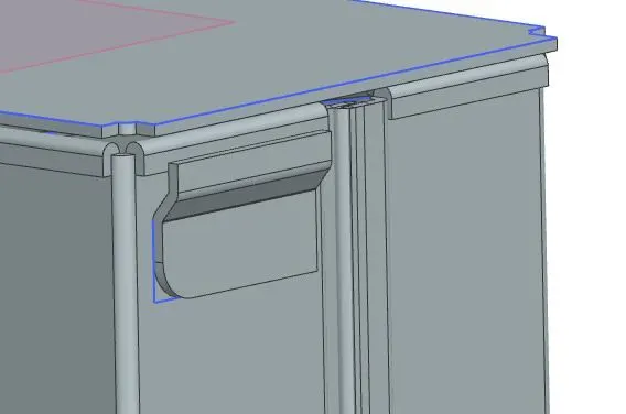
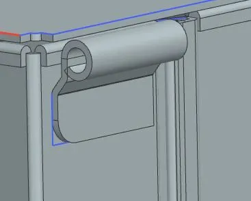
*Performong of HEM:
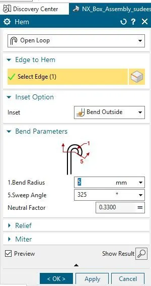
* Select the Hem option ans select the edge .
* Moreover , chage the loop option from closed loop to open loop and select the required edge .\
* Giving the inset to bend outside ,with the bend parameter of bend radius 5mm and the angle to 325 as shown below ;
* Before performing Hem :
* After performing Hem :
* Performing the model with Unbend option:
UnBend : The process that flatters thesurface with respect to selected surface .
* Select the unbend from bend tool bar and select a surface as required to make a flat surface ,a ideal surface .
* Furthermore ,click ok to continue the process as shown below .
* Model before using unbend :
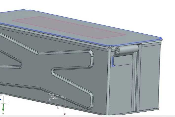
* Model After using unbend :
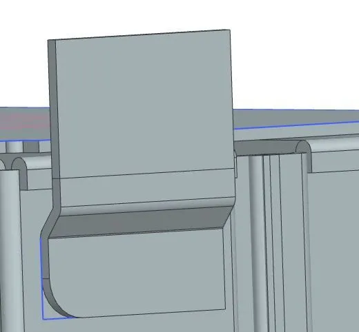
* Performing of Normal Cutout .
Normal Cutout : The Process that cuts the material by projecting a sketch onto the model and then cutting perpendicular to teh faces Intersected by the projection.
*Before performing normalcutout the sketch id required .
*From tool bar select sketch and also select the surface where the sketch has to be performed .
* Select the surface and click to sketch .
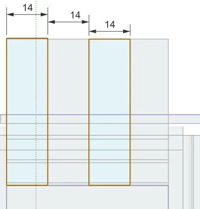
* Futhermore,draw a rectangle as given parameters .
* After completion of sketch click to finish as show below ;
* Model before performing Sketch :
*
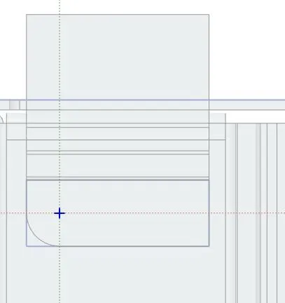
* Model After performing Sketch :
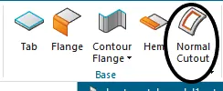
* Now select Normal cutout from base tool bar and select the sketch which need to be cutout.
*Select the sketch and click ok as shown below :
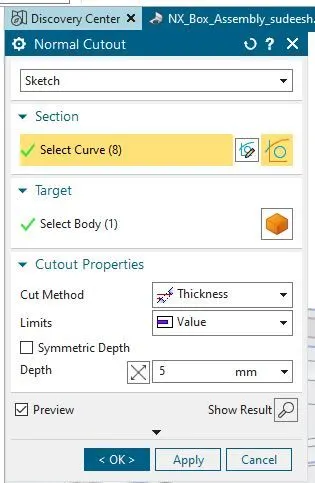
* Model before Normalcutout :
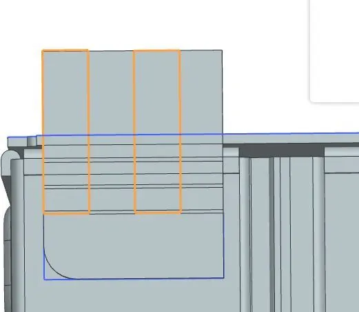
* Model After Normalcutout :
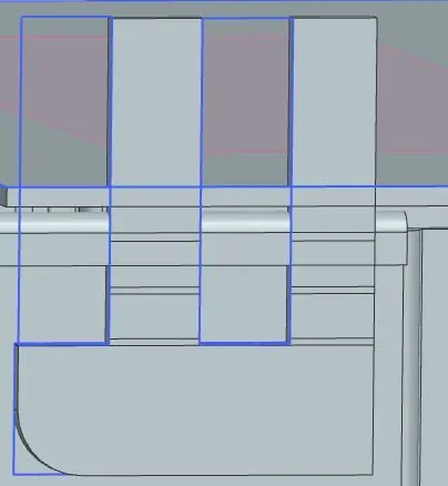
* Now, from Bend tool bar select the rebend and Drag the surface which are required as shown below;
* Model before using Rebend :
* Model After using Rebend :
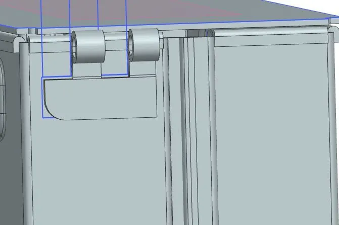
* Performing of Mirror option :
* As mirror option is already performed in for before features ,select mirror features from tool bar.
* Select the bead feature and sketch which to be mirror .
*Moreover ,select plane to which the mirrored feature need to be placed and click apply as shown below .
* Model before Performing Mirror feature :
* Model After Performing Mirror feature :
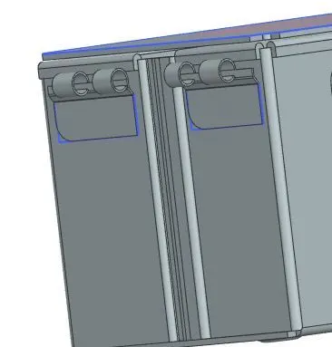
* Performing of tab in top surface .
* select sketch from toolbar and select the top plane for sketching .
* Draw a rectangle as needed sketch parameters .
* After sketching of rectangle ,from tool bar select tab and select the sketch to be performed tab .
* After completion of sketch click to finish as show below ;
* Surface before sketching :
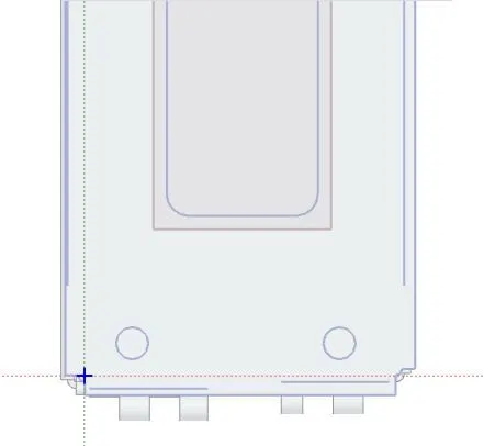
* Model after sketching :
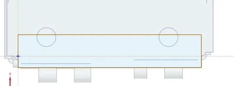
* Model After performing Tab option :
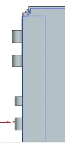
* Performing of break corner:
* From tool bar select break corner and selec the edge .
*Give the corner radius as 10 mm as shown below .
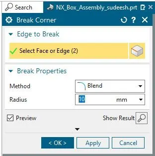
* Model before performing break corner :
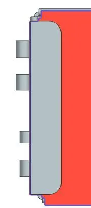
* Model After performing break corner :
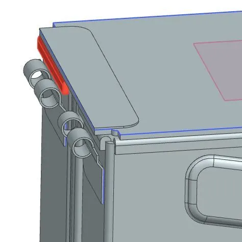
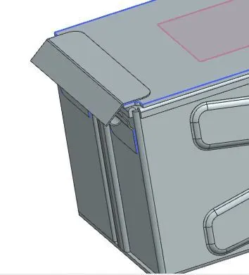
* Performing of Flange option:
* From tool bar select flange option and select the edge.
* The process are shown below .
* Model before flange :
* Model After flange :
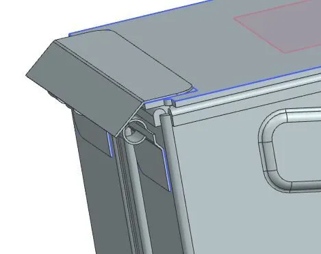
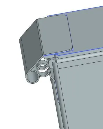
* Select the Hem option ans select the edge .
* Moreover , chage the loop option from closed loop to open loop and select the required edge .\
* Giving the inset to bend outside ,with the bend parameter of bend radius 5mm and the angle to 325 as shown below ;
* Before performing Hem :
* After performing Hem :
* Performing of Unbend :
* Select the unbend from bend tool bar and select a surface as required to make a flat surface ,a ideal surface .
* Furthermore ,click ok to continue the process as shown below .
* Model before using unbend :
* Model After using unbend :
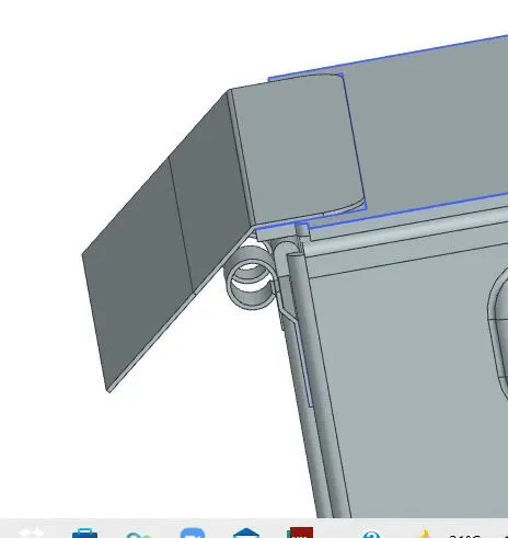
* Sketching the model before normal cutout :
* From tool bar select the sketch option and selec the plane where need to be sketched .
* Draw a rectangle in selected plane with given dimensions as shown below :
* After completion of sketch click to finish as show below ;
* Surface before sketching :
* Surface After sketching :
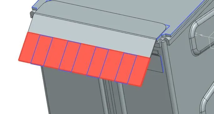
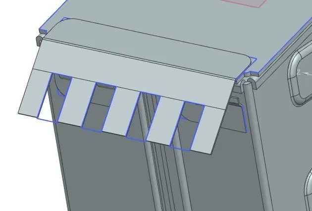
* Performing of Normal cutout :
* Now select Normal cutout from base tool bar and select the sketch which need to be cutout.
*Select the sketch and click ok as shown below :
* Model Before Normal cutout:
* Model After Normal cutout:
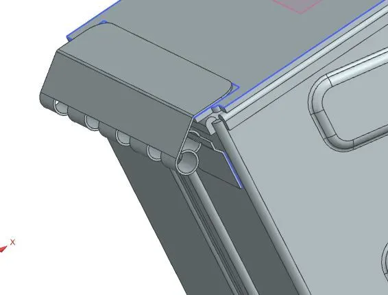
* Performing of Rebend Option :
* Now, from Bend tool bar select the rebend and Drag the surface which are required as shown below;
* Model before using Rebend :
* Model After using Rebend :
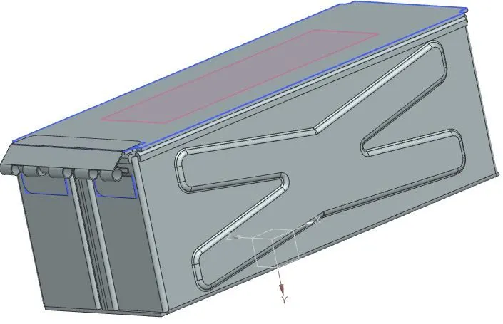
* Final Model after completion :
* Isometric view:
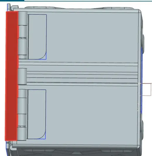
* Front View :
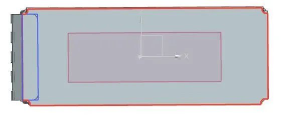
* Top View :
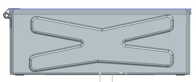
* Side View :
* Conclusion : The report on sheet metal component can be performed with dimensions as given above .