Advanced Sheet Metal Design Using NX Cad Challenge_2_Box Assembly
BOX ASSEMBLY USING NX CAD
AIM:
To create a sheet metal component of Box Asssembly in NX cad tool and to explain with detail report.
INTRODUCTION
Sheet metal is a metal forming process through industrial process into thin, flat pieces. Here, I have created a Sheet Metal Box assembly of Various thickened parts. Box assembly contains 3 main parts.
- Box (base part)
- Box Lid
- Hinge
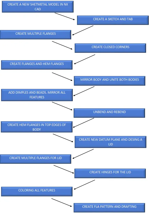
To design this parts I have used NX sheet metal workbench. Design methodology I have used to design this is described below.
DESIGN METHODOLOGY:
TOOLS DESCRIPTION:
SKETCH TOOLS:
Sketching is the process of creating a 2D drawing before developing it in 3D. In Siemens NX Sheet Metal, there are plenty of options and has various tools for creating a 2D sketch. In that, a few tools that are used for drawing the casing are discussed below.
TAB:
It is used to create a base feature by extruding a sketch along a vector by a thickness value or adds material to a planar face. Additional planar selections can be added to generate bends as part of the base feature.
FLANGE:
It is used to add a flat flange at an angle to a planar face and adds a bend between the two.
BEND
It is used to modify a model by bending material on one side of a sketch line, adding a bend between the two sides.
BREAK CORNER:
It is used to create rounds or chamfers around sharp corners of a tab or flange
DIMPLE:
It is used to lift an area of the model inside a sketch that simulates a stamping tool.
BEADS.
It is used to lift the material along the contour of a sketch that simulates a stamping tool.
HEM FLANGE:
This is used to modify by folding the edge of a sheet metal flange over onto itself for the purpose of safe handling or to increase edge stiffness.
NORMAL CUTOUT:
It is used to create cut material by projecting a sketch onto the model and then cutting perpendicular to the faces intersected by the projection.
UNBEND:
It is used to flatten a bend and the material adjacent to the bend.
REBEND:
It is used to restore an unbend feature to its previous bend state, along with any features added after the unbend feature.
FLAT PATTERN:
The Flat Pattern feature is intended to be used on drawings and for export to Sheet metal manufacturing.
MODELLING PROCEDURES:
CREATE A TAB:
Click in “Tab” button to create a rectangular sheet metal of 1mm thickness.
By default, the section part will be highlighted and hence select the rectangular sketch which is drawn in the previous step – then click ok.
This will create a Tab of 1mm thickness.
CREATE MULTIPLE FLANGES:
Use Flange Feature and select appropriate edges to create flanges normal to XY & XZ Plane respectively.
CREATE CLOSED CORNERS:
Use Closed Corner and select bends of adjacent flanges to close the corners.
CREATE MULTIPLE FLANGES
Use Flange Feature and select appropriate edges to create flanges normal to XY & XZ Plane respectively.
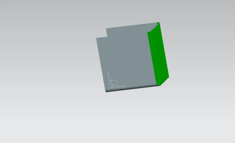
CREATE MULTIPLE HEM FLANGES:
Create an open type Hem flange by selecting edge of flange created before. Do the same on the other edge too.

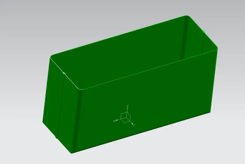
CREATE MIRROR BODY:
Using “Mirror body” tool ,Select the Created body and mirror it about YZ Plane.
UNITE BODY:
Use the two bodies (Created & mirror body) to unite.
ADDING A DIMPLE & MIRRORING IT:
Select the Side face of the Box and Create a sketch in the shape of "X". Apply sketch fillets to the edges to round the corners and connecting edges.Use Dimple feature to create a stamp on it.Mirror the above created dimple about XZ Plane using Mirror feature.
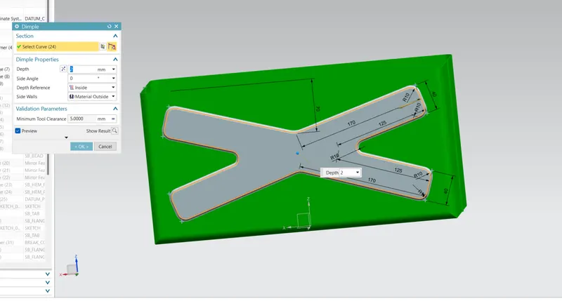
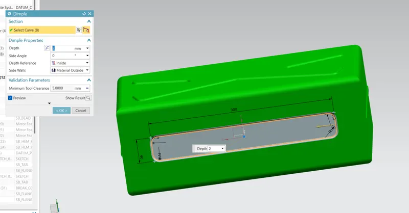
ADDING DIMPLE AT BOTTOM.
Select the Bottom face of the Box and Create a sketch using rectangle. Apply sketch fillets to the edges to round the corners.
Use Dimple feature to create a stamp on it.
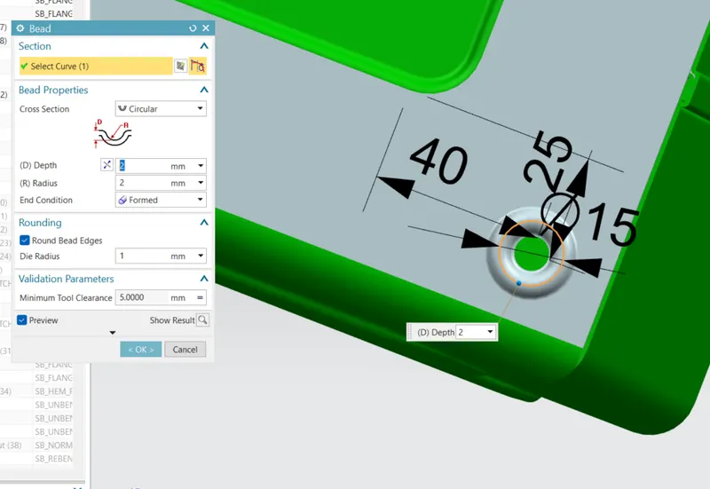
CREATE BEAD IN BOTTOM FACE.
Select the Bottom face of the Box and Create a sketch using Circle.
Use Bead feature to create a stamp on it.
Mirror the above created dimple about X & Y Axis using Mirror feature.
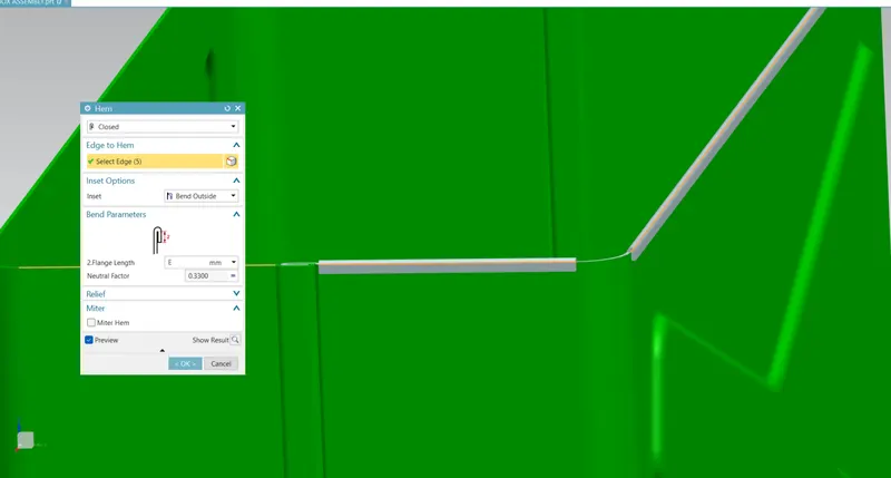
CREATE HEM FLANGES IN TOP EDGES.
Select the top edges and use Closed type Hem flange to fold the material.
CREATE A LID
Create a Datum plane at an offset of 203mm from bottom face.
Now sketch on newly created plane using lines and arcs in such a way that it forms a lid shape.
Use Tab feature and select the sketch to create Lid.
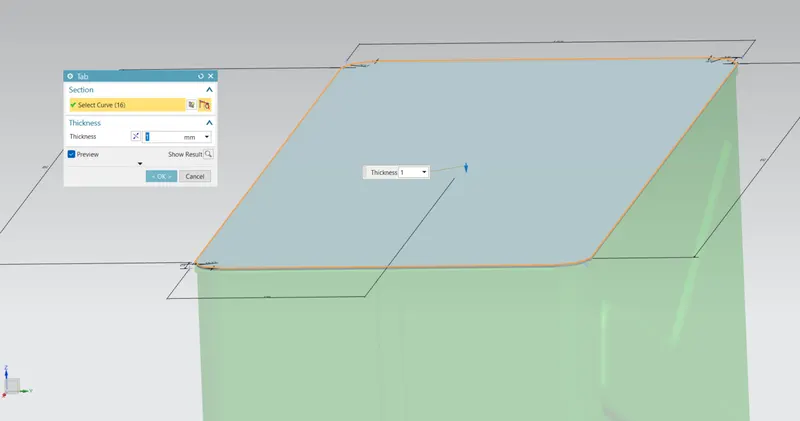
Extend the edges of lid by using Flange feature.

CREATE HINGES IN BODY
Create a Sketch on side face by drawing a rectangle. Exit the Sketch.
Create a Tab by selecting above sketch.
Use Break corners and select the bottom left edge to round it.
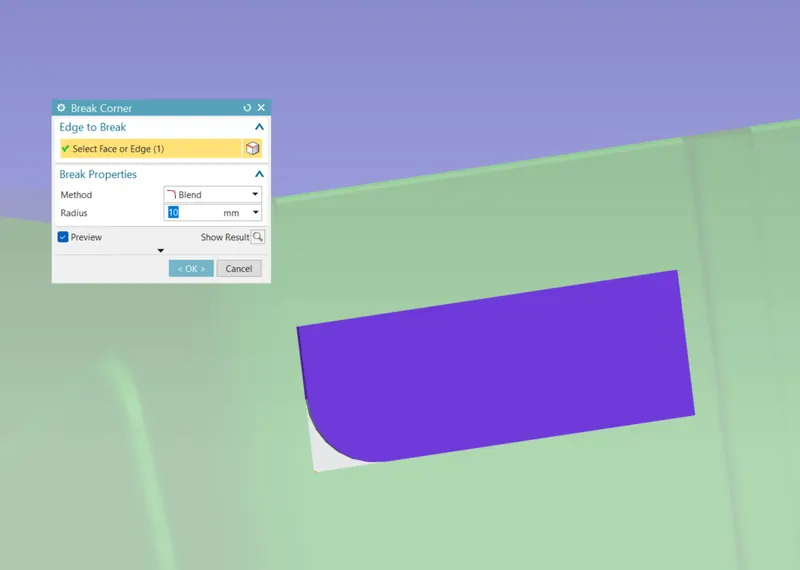
Create a flange at an angle by selecting edge of previously extruded Tab.
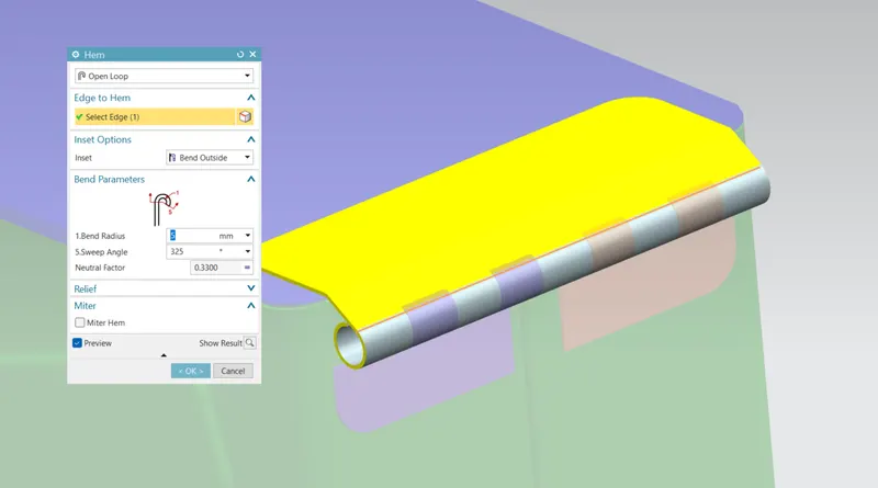
Now use Open loop type Hem. flange by selecting proper edge to create a fold.
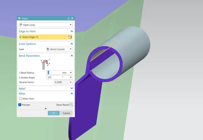
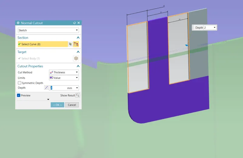
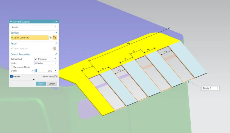
Unbend the fold and created a sketch by drawing few rectangle. Exit the Sketch and do Normal cutout.
Re-bend the fold.
Mirror created hinges by usning xz plane
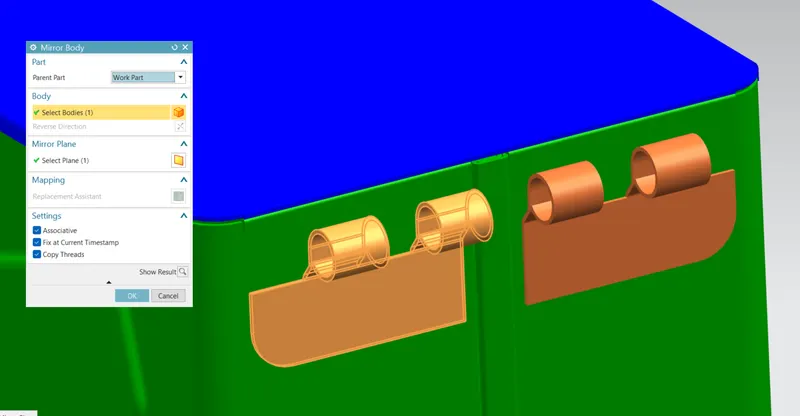
CREATE HINGES IN LID
Create a Sketch on top face by drawing a rectangle. Exit the Sketch.
Create a Tab by selecting above sketch.
Use Break corners and select the top left & right edges to round it.
Create a flange at an angle by selecting edge of previously extruded Tab.
Now use Open loop type Hem. flange by selecting proper edge to create a fold.
Unbend the fold and created a sketch by drawing few rectangle. Exit the Sketch and do Normal cutout.
Re-bend the fold.
ISOMETRIC VIEW,
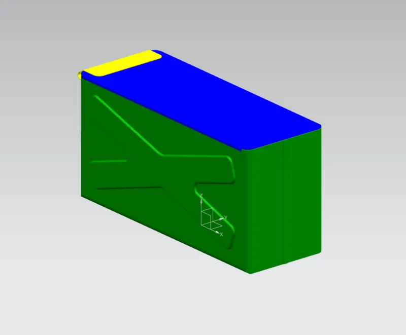
TOPE VIEW,
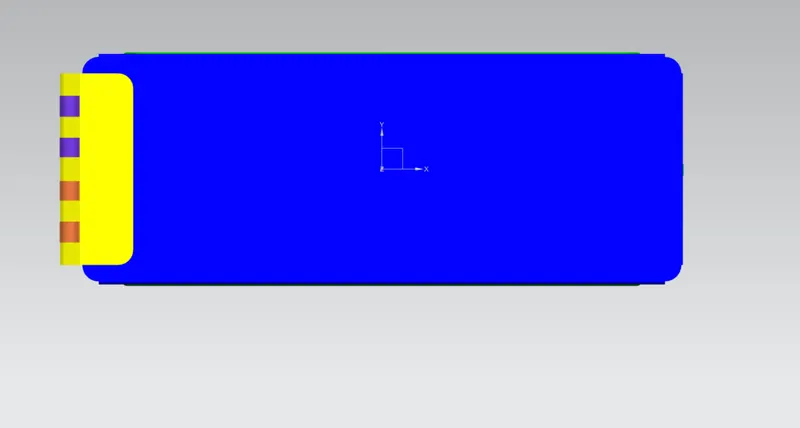
BOTTOM VIEW,
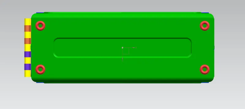
FRONT VIEW,
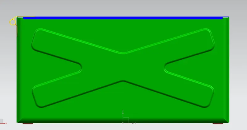
LEFT SIDE VIEW,
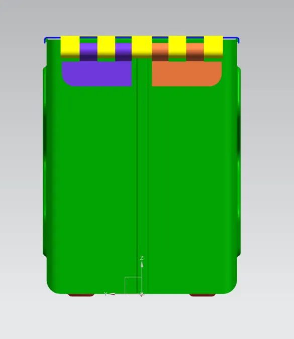
RIGHT SIDE VIEW.
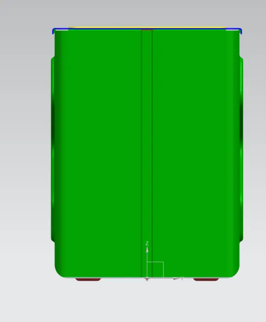
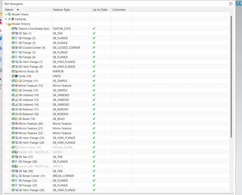
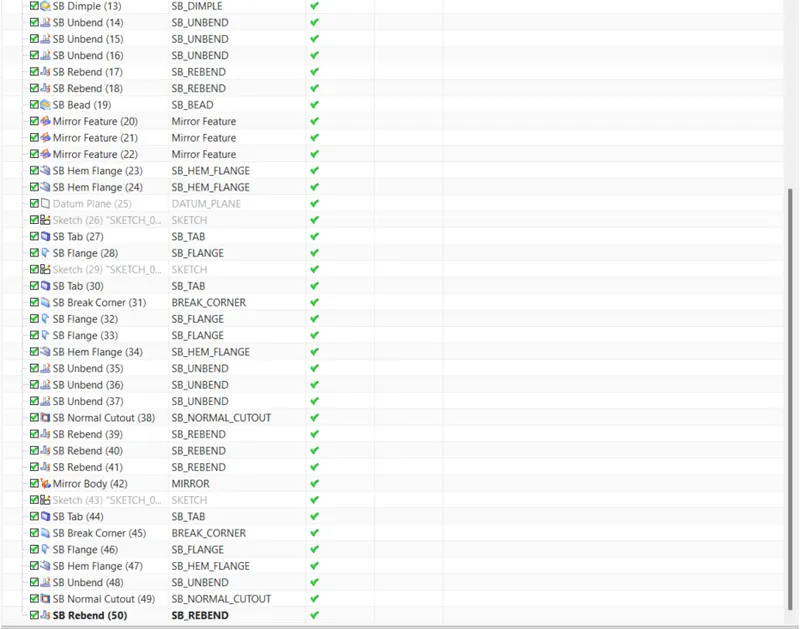
FEATURE TREE.
DRAFTING .
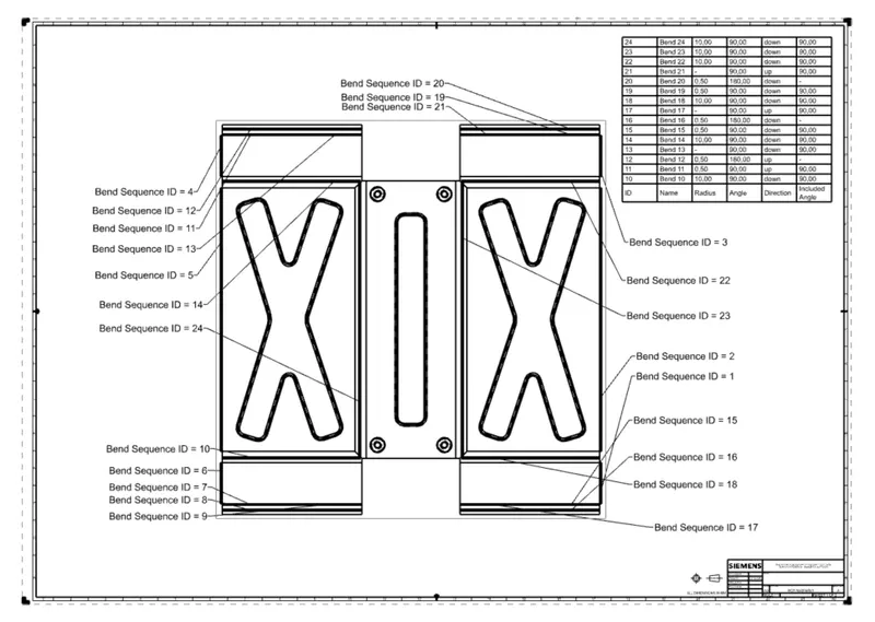
We can create 2D drawing sheets in NX CAD from the sheet metal component designed.
CONCLUSION
Finally, we created sheetmetal comopnent of Box assembly and drafting the component using flat pattern view and explained in detail.