Advanced Sheet Metal Design Using NX Cad Challenge_2_Box Assembly
BOX ASSEMBLY
Objective: To design the given sheet metal component "Box Assembly" with given dimensions and making a report about tools and features used for the component using Siemens NX CAD software.
Introduction:
The given sheet metal component "Box Assembly" is an example to pratice and make familiar with the tools and features in sheet metal operation. This component is sketched and designed as per the given dimensions with accurate.This design consists of a closed box with a box lid upon the box and both joined with the use of rotating hinges.
Design methodologies:
1. Sketching the given shape
2. Construction of basic features
3. Addition of other features needed
4. Performing unbending, rebends, beads and dimples
Features and Tools:
1. Sketch: It creates a sketch in the current application. Use the direct sketch tools to add curves, dimensions, constraints, etc.
2. Tab: It creates a base feature by extruding a sketch along a vector by a thickness value, or adds material to a planar face. Additional planar selections can be added to generate bends as part of the base feature.
3. Flange: This is used to add a flat flange at an angle to a planar face and adds a bend between the two.
4. Closed corner: It is used to close a corner where two adjacent flanges meet by extending the bends and flanges.
5. Hem flange: It modifies the model by folding the edge of a sheet metal flange over onto itself for the purpose of safe handling or to increase edge stiffness.
6. Mirror body: This feature copies a body and mirrors the body across a plane.
7. Unite: This feature combines the volume of two or more solid bodies into a single body.
8. Dimple: This is used to lift an area of the model inside a sketch that simulates a stamping tool.
9. Unbend: This feature flattens a bend and the material adjacent to the blend.
10. Rebend: It restores and unbend feature to its previous bent state, along with any features added after the unbend feature.
11. Bead: This feature is used to lift the material along the contour of a sketch that simulates a stamping tool.
12. Break corner: This feature rounds or chamfers a sharp corner of a tab or flange.
13. Normal cutout: This feature cuts the material by projecting a sketch onto the model and then cutting perpendicular to the faces intersected by the projection.
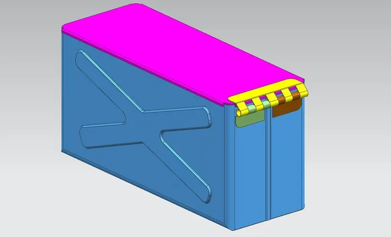
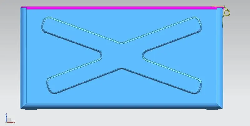
Trimetric view Front view
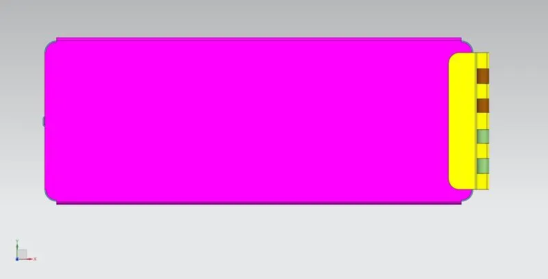
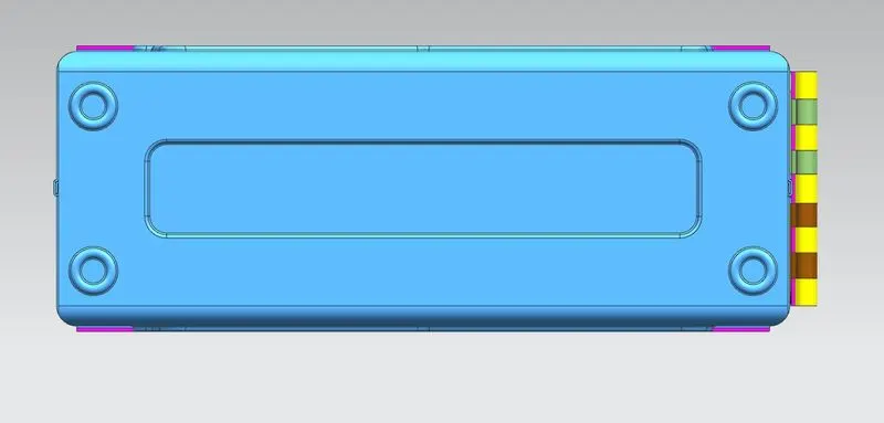
Top view Bottom view
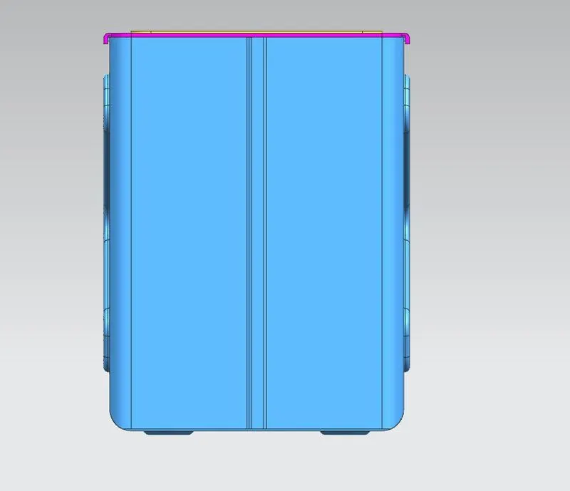
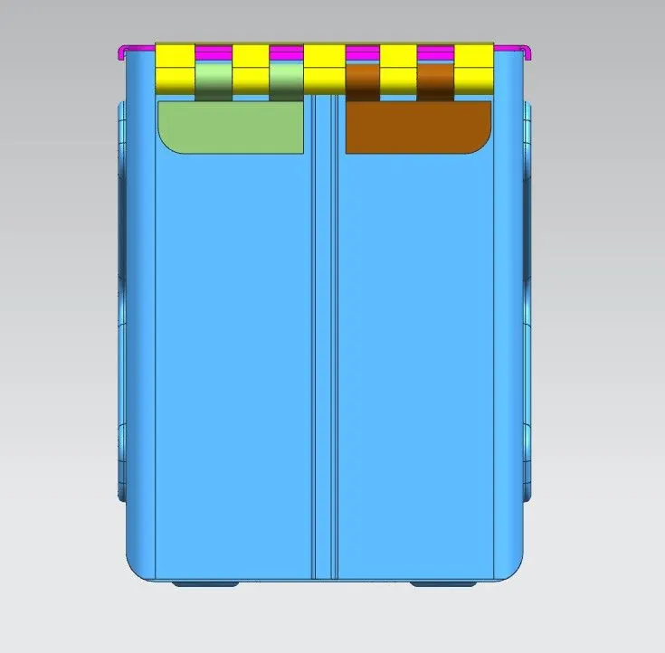
Left view Right view
Conclusion: So the required sheet metal component Box Assembly has been designed with given dimensions by using Siemens NX CAD software and the final output results are shown above.