Advanced Sheet Metal Design Using NX Cad Challenge_2_Box Assembly
DESIGN A SHEET METAL BOX ASSEMBLY USING UG NX CAD
AIM :
To modelling a sheet metal box assembly using nx cad.
OBJECTIVE :
- Modelling of box Assembly.
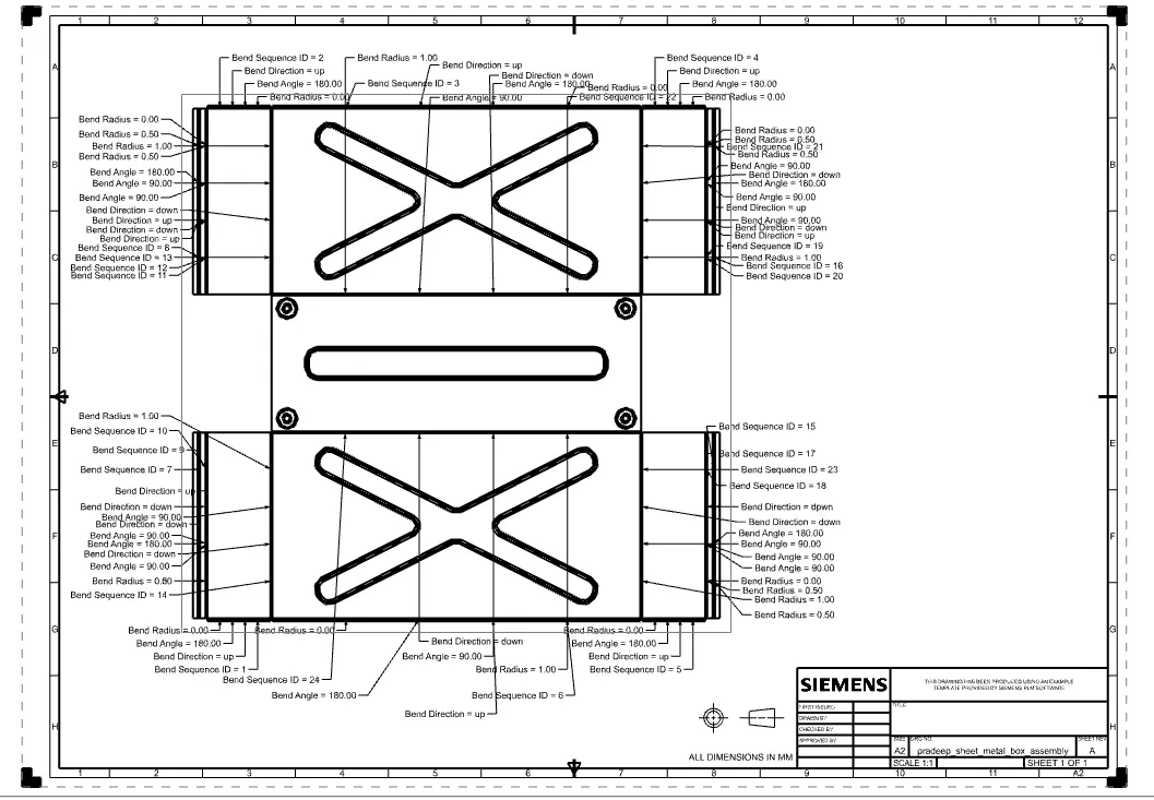
- Drafting of the designed part in A2 sheet.
Design Methodology :
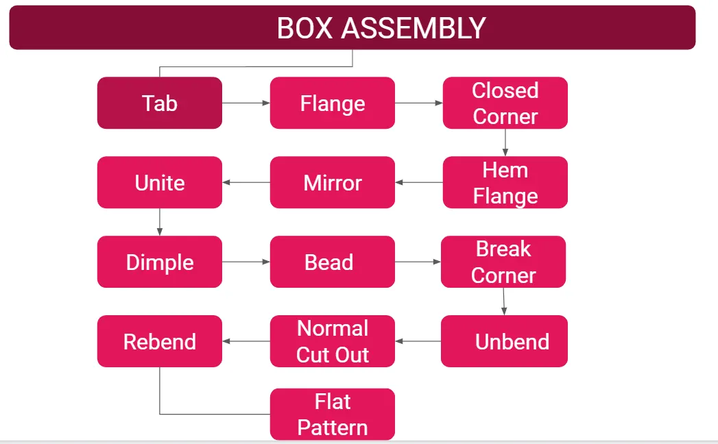
INTRODUCTION :
Sheet metal box is used for storage purpose.
Tools used to desidn this part,
- Tab - Creates a base features by extruding the sketch along the vector by a thickness value or adds material to the planar face.
- Flange - Adds the flat flange at the given angle.
- Closed Corner - Closes the corners where two adjecent flanges meet by extending the bends.
- Hem Flange - Modifies the model by folding the edges of sheet metal flanges
- Mirror - Copies the bodies or features across the selected plane.
- Unite - Combines the volume of two or more solid bodies into a single body
- Dimple - Lifts an area of model in a sketch.
- Bead - Lifts material along the contour of the sketch that simulates a stampling tool.
- Break corner - Rounds or chamfer the sharp edges of tab & flanges
- Unbend - Flattern the bends and material adjecent to the bend.
- Normal Cut Out - Cuts material perpendicularly by projecting the sketch onto the model.
- Rebend - Restore the unbend command to its previous bend state.
- Flat pattern - Creates the flat pattern features from the formed sheet metal parts.
Box Front View :
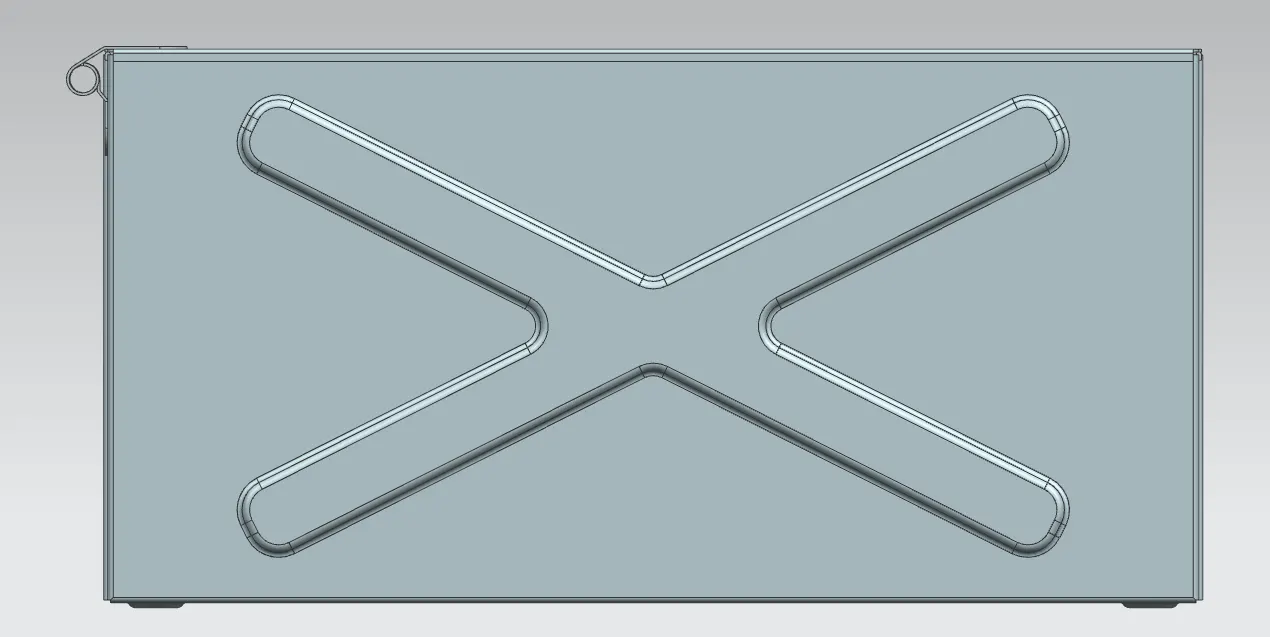
Box Side View :
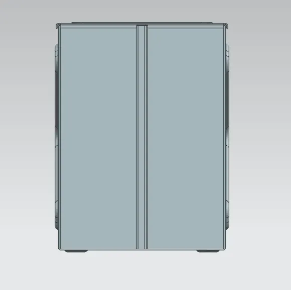
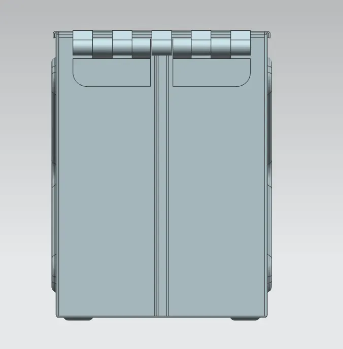
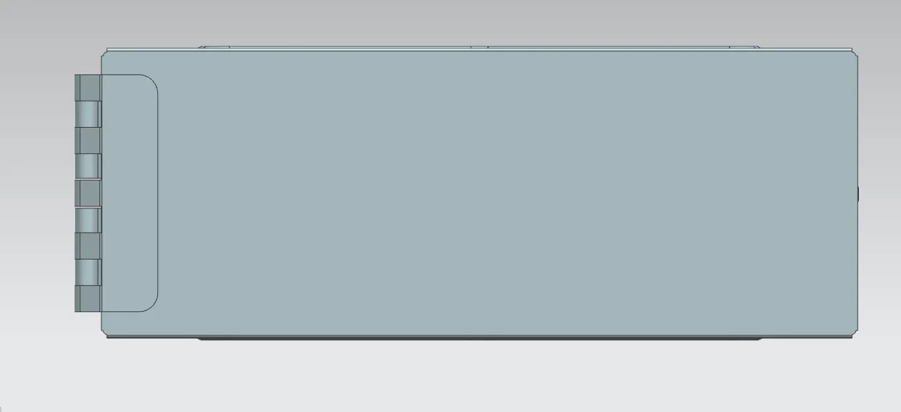
Box Top View :
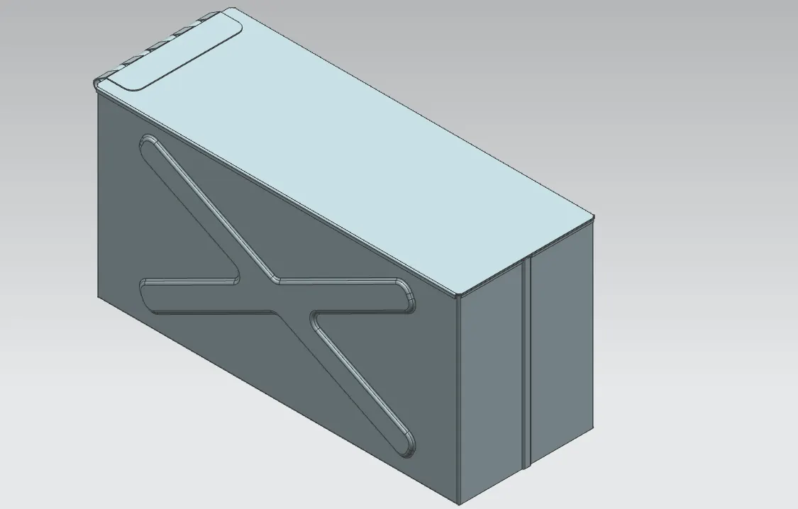
Box Isometric View :
Box Drafting :
Link For the part : https://drive.google.com/file/d/18u-4Z2-rwGoZtP1t7-fz9ZFZUn8DQGJa/view?usp=sharing
CONCLUSION :
Thus the design, modellind & drafting of Box assembly using nx cad is completed sucessfully.