Advanced Sheet Metal Design Using NX Cad Challenge_2_Box Assembly
BOX ASSEMBLY
Objective:
The objective of this challenge is to design a box assembly using advanced sheet metal application in Siemens NX.
Introduction:
Sheet Metal is application which is widely used in construction of various products in various fields around the globe every day.
Sheet metal application is mainly used in industries like Automobile, aerospace, fixture fields.
The construction of outer surface of the cars and flights and many other involves sheet metal operations like bending, cutting to get the required shape.
The reason behind using sheet metal application rather than any other application is because of its ease of manufacturing, transporting and it has resistance from any harsh weather conditions.
Design methodology:

Description:
1.Designing of the box
Designing of the box involves various operations as follows
1.TAB: In this operation we can create one base for the box, we have created one base sketch and created and created one tab with thickness of 1MM.
2.FLANGE: We have created one pair of flange with normal to XY plane with a length of 200MM. After that we need to create another pair of flange normal to XZ plane so that we get the closed 4 walls of the box.
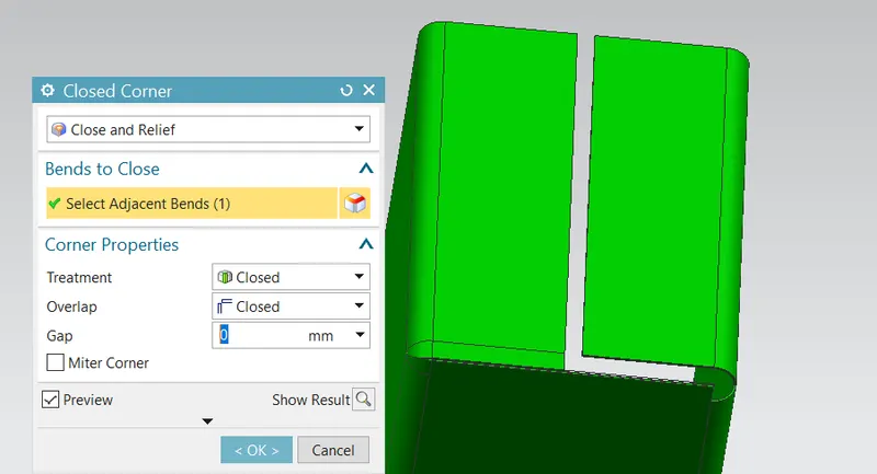
3.CLOSED CORNER: This is the operation used for creating one corner for the edges of the box, simply it connects tabs with flanges of the box. For this we have used a closed and relief corner, the corner properties are closed in overlap with 0MM gap.
4.CREATING A HOOK: For this we need to create one Flange with Bend Radius 0 and Length 0.02 on the face of the flange normal to XZ that we earlier created. After that create another flange with length 6.5MM but “make sure that for this flange you have to use BENT OUTSIDE as the inset option.”

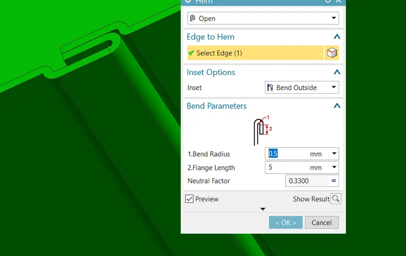
5.HEM FLANGE: In this operation the creation of hook will be completed, after creating the flange with 6.5mm length you have to create one hem flange open type with bend radius 0.5mm and 5mm length.
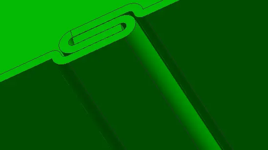
6.MIRROR BODY: In this operation we will mirror the body with respect to the YZ plane.
7.UNITE: This operation is used to combine the mirror body and sheet metal body into one single body.
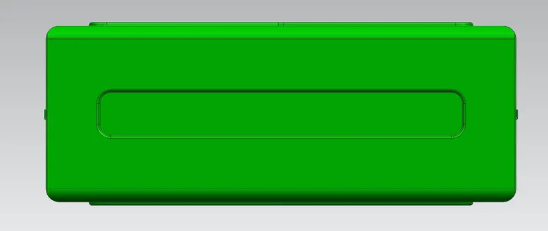
8.DIMPLE: This is used to lift some area along the sketch it reduces the weight of sheet metal and also increases the strength and rigidity, here we have used one dimple with 2mm depth.
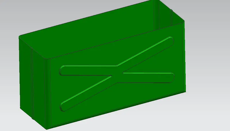
9.MIRROR FEATURE: Use this operation to mirror the dimple across the plane (i.e.) on the other side of the box.
10.DIMPLE: Create another dimple on the base of the box the shape of this dimple resembles the rectangle use the same properties such as 2mm depth for this dimple too.
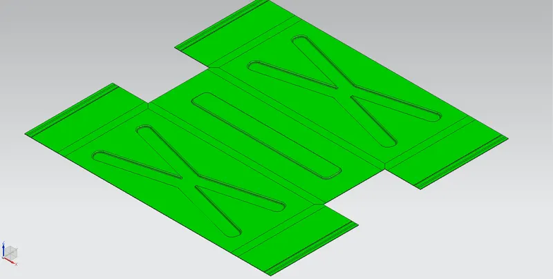
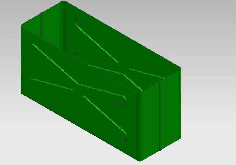
11.UNBEND AND REBEND: In this operation we will ensure the sheet metal design that we have created can be manufactured by unbending with respect to one base face and rebending it again.
12.BEAD: In this operation we have created one circular bead on outer surface of the base and using mirror feature we have make sure that bead is created on four sides on the base.
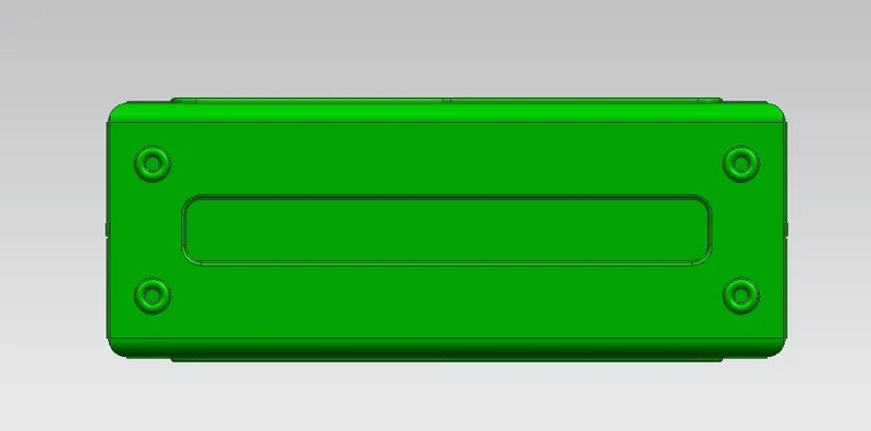
13.HEM FLANGE: We need to create hem flanges on every side of the of box as shown.

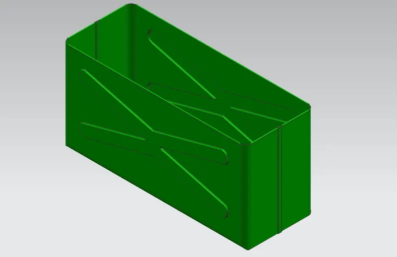
The box is created by the above steps and the final output of the box will be as follows.
2.Designing of lid for the box
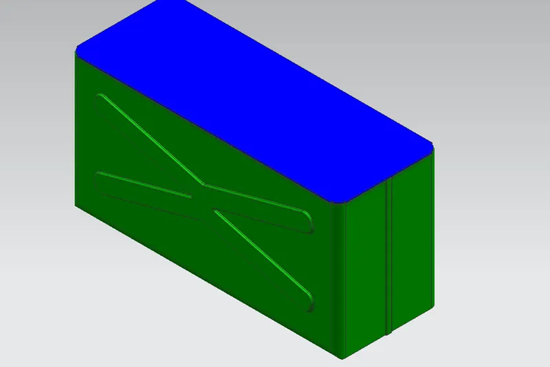
1.DATUM PLANE: Create one datum plane with distance of 203mm from base of the box, this plane is used for creating sketch for the lid.
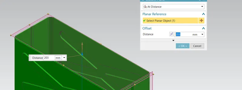
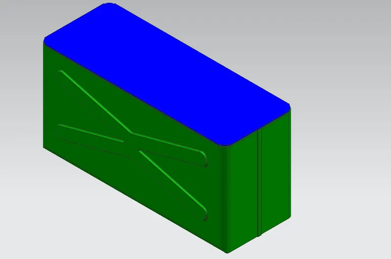
2.DESIGNING THE LID: For this we have used project curve option on the faces of the box, after projecting every curve use corner option.
After this create one tab for this sketch with 2mm thickness.
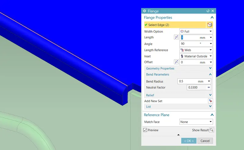
3.CREATING FLANGES: At the ends of the tab create flanges with bend radius 0.5mm and length 3mm.
Then the lid is created with the given inputs as shown below.
3.Designing of HINGE:
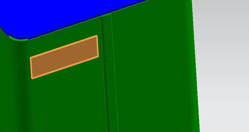
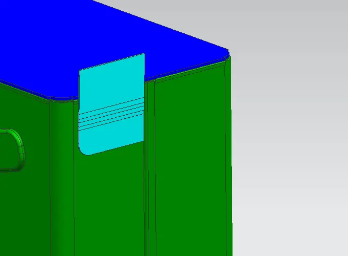
1.CREATING TAB: Create one tab on the face of the box with 1mm thickness as shown.
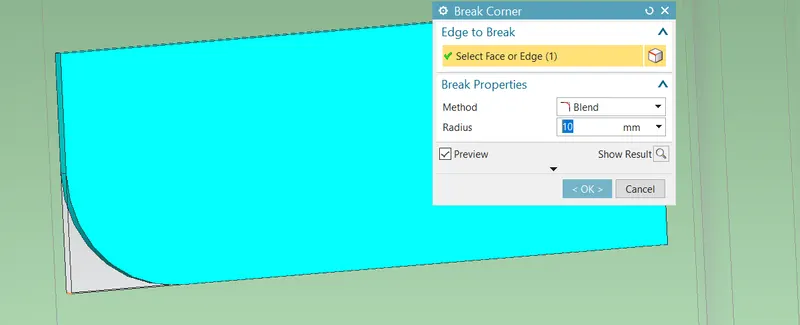
2.BREAKE CORNER: On the corner use 10mm radius break corner.
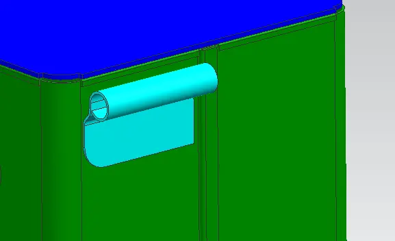
4.FLANGE AND HEM FLANGE: Create one flange on this tab with 40deg angle and 4mm length. After creating the flange, use Hem flange with bend radius 5mm and 325deg sweep angle.
5.UNBEND AND NORMAL CUTOUT: Use unbend option for unbending the hinge and make slots on it by using normal cutout option.
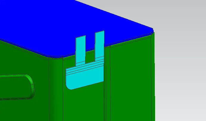
6.REBEND AND MIRROR BODY: Now rebend this hinge assembly and mirror it to other side for this you can use datum plane with bisector option.
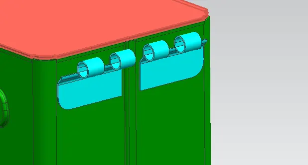
7.CREATING HINGE ON THE LID: Create one tab on the lid with 1mm thickness and give break corner of 10mm on both sides of that tab as shown in fig.
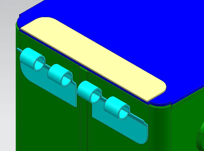
After that create one flange to that tab with 13mm length an 39deg angle.
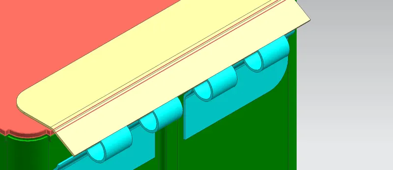
Create one hem after that with bend radius 5mm and 325deg angle.
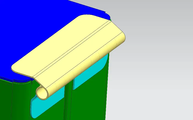
Use unbend option and create slots on it with respect to the hinge on the box using Normal cutout option.
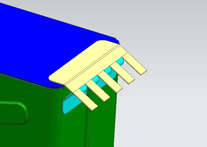
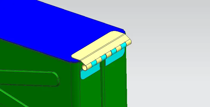
Rebend this hinge the Hinge assembly connecting the box and lid has been created as shown below.
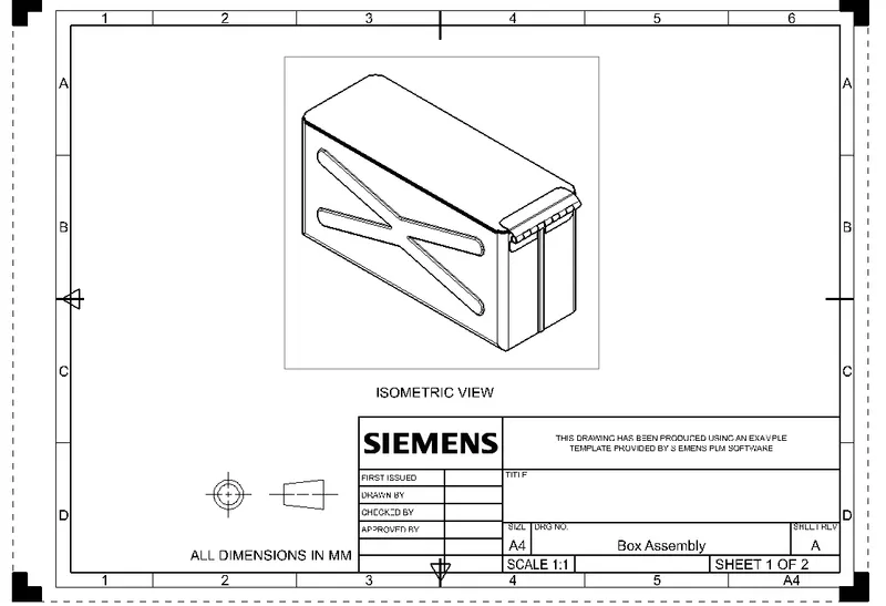
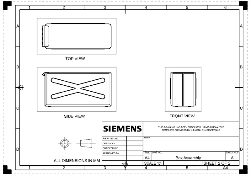
DRAFTING:
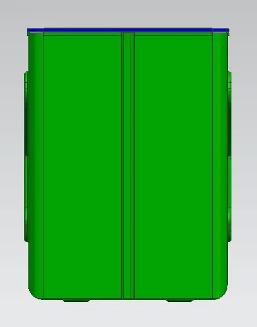
FRONT VIEW :
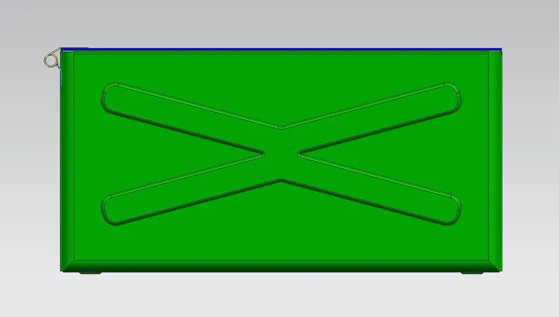
SIDE VIEW :
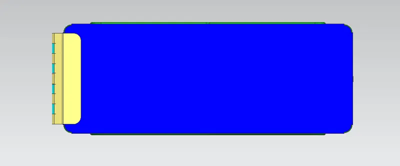
TOP VIEW :
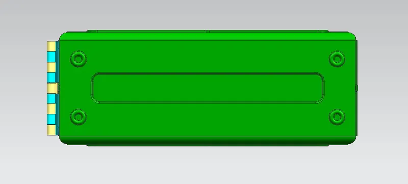
BOTTOM VIEW :
CONCLUSION:
In this challenge the box assembly is designed and drafted using advanced sheet metal application of Siemens NX.