Advanced Sheet Metal Design Using NX Cad Challenge_1_Casing Design
CASTING DESIGN USING ADVANCED SHEET METAL DESIGN
OBJECTIVE:
The objective of this challenge is to understand the commands used in Advanced sheet metal application of NX software, various design parameters to consider while working in sheet metal application software and design a casting in sheet metal application of NX.
INTRODUCTION:
Sheet metal is used for manufacturing of locomotives mainly it is used manufacturing the body of the cars, bikes. It is also used in aviation industry for creating the outer bodies of flights.
Sheet metal is a thin piece of metal whose thickness is less and can bend into required shape in manufacturing industry.
The main reason of using of sheet metal in various industries are because of characteristics like having high strength, easy to bend into required shape, corrosion resistance etc.
The manufacturers choose they own material for manufacturing the sheet metal, in industry the material is rolled into thin piece of material of required thickness this can be cut, bended into required output
Design methodology:
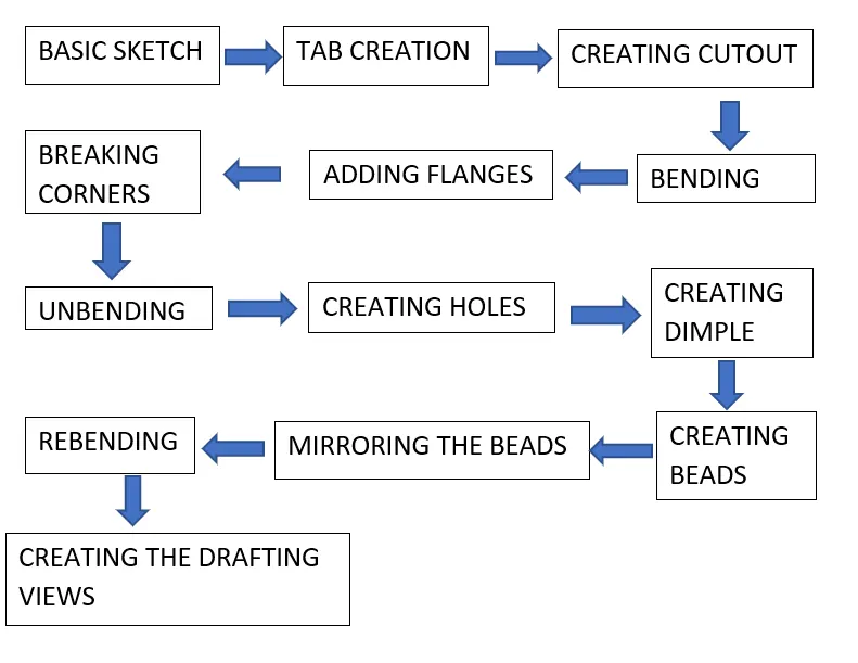
The methodology for creating the casting is as follows
Description:
Basic Sketch:
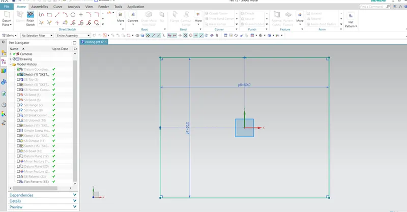
In the first step of designing casting, we need to create the sketch for creating the tab for our casting.
Tab Creation:
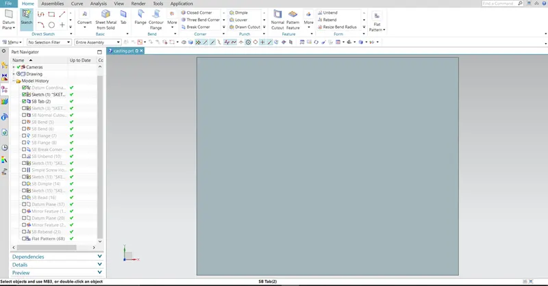
From the sketch we get the outline of the tab, by using this sketch we can create one tab of desirable thickness.
Above shown is the tab of 1mm thickness.
Creating cutout:
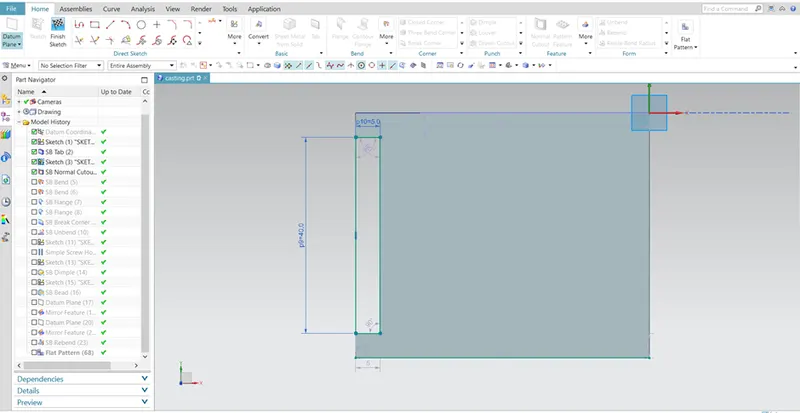
We need to create one cutout as shown for that create one sketch on the face of the tab.
After finishing the sketch, select the Normal Cutout option for creating the above shape.
Bending:
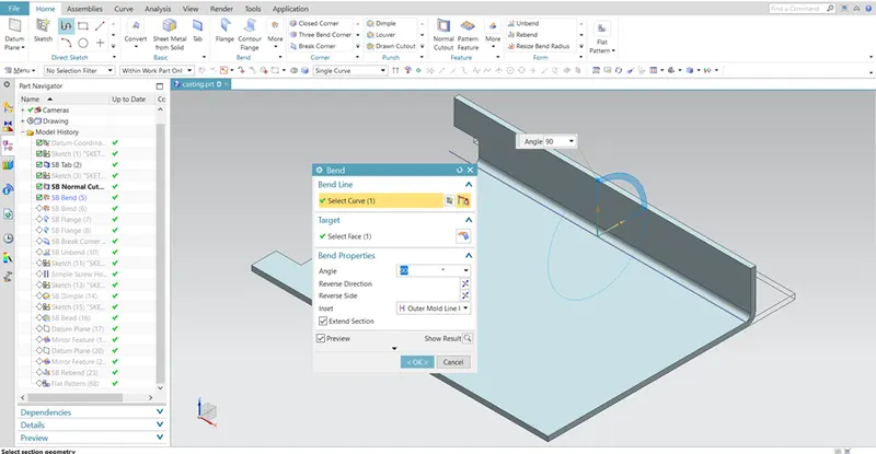
After creating the cutout, we need to create bend on our tab for that select bending option and draw one line from one edge.
Select the line as the bend line and select the target face as the tab, create the bend of angle 900 to the tab.
Adding flanges:
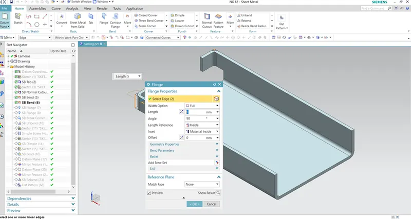
Create two pair of flanges on the model one will be facing each other as shown, and another pair will be facing opposite.
The length of flanges will be 5mm and the angle is perpendicular to the reference face.
Breaking corners:
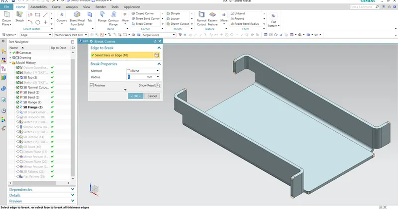
This option is used to blend the sharp edges present on the model, use BREAK CORNER option and select the method as blend and select all the edges with sharp corners for creating above model.
Unbending:
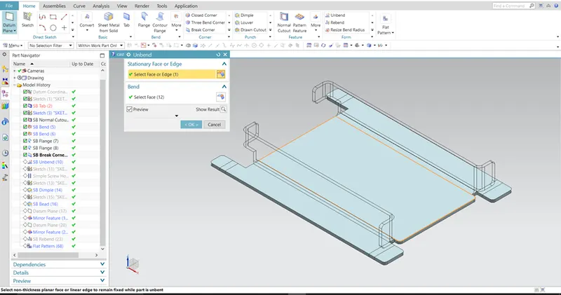
There are some advanced features in NX software that can be performed by unbending the sheet metal, in upcoming steps we can see some of those features.
For unbending the sheet metal, we have to select one stationary face as shown in the fig.
Creating holes:
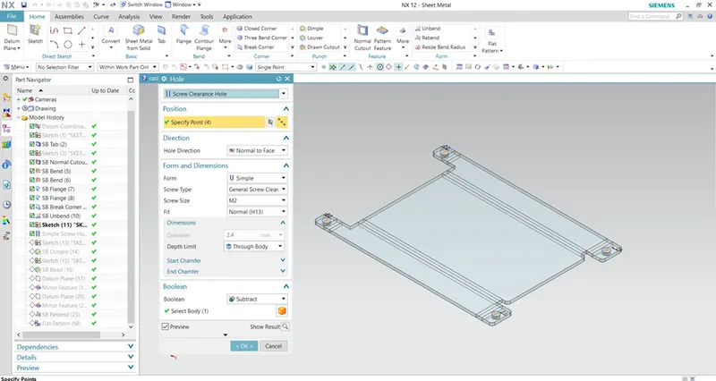
Draw one line on the face of the model and create one point at the middle of that line now create holes by taking the points as the reference. Screw size is M2 with H13 fit.
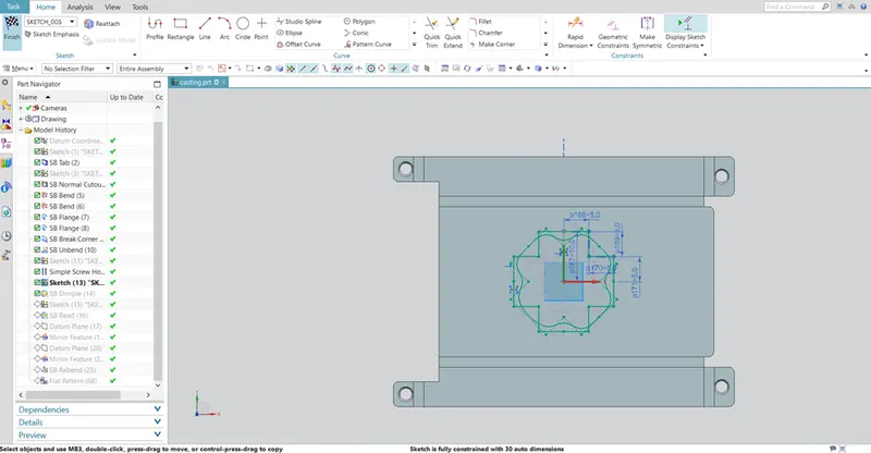
Create one sketch with 5mm length around the origin on XY-plane and create one spline using spline studio command.
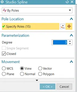
Select the option by poles with closed parameterization as
Shown in the fig and rotate the spline 450 with respect to the Origin.
Creating dimple:
This feature is used to lift some portion of the sheet metal, dimple reduces the weight of the sheet metal by increasing its rigidity and strength.
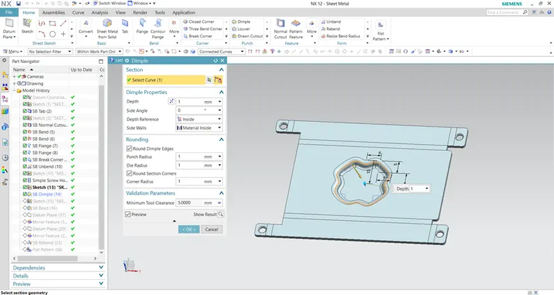
Create one dimple for that spline as shown in the fig.
The depth of dimple is 1mm.
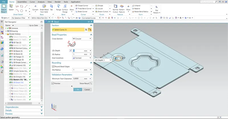
Creating beads:
Beads are one of the advanced sheet metal applications which will used to lift some material as per the sketch on the sheet metal.
This will also give the structural strength and rigidity to the sheet metal.
Unlike dimples sketches used to create beads can be closed or opened.
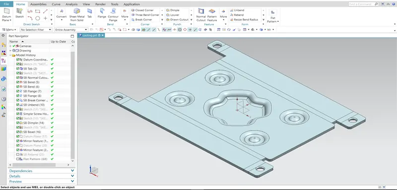
Mirroring the beads:
On our casting we need four dimples as shown above, for that we can use MIRROR FEATURE.
Create one datum plane on YZ face of WCS-absolute and mirror the dimple, do it again by creating datum plane on XZ face of WCS for getting above result.
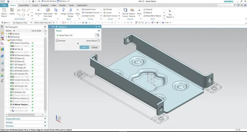
Rebending:
Now that all the advanced applications on the casting have been performed, we can rebend the casting into original shape as shown.
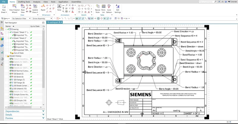
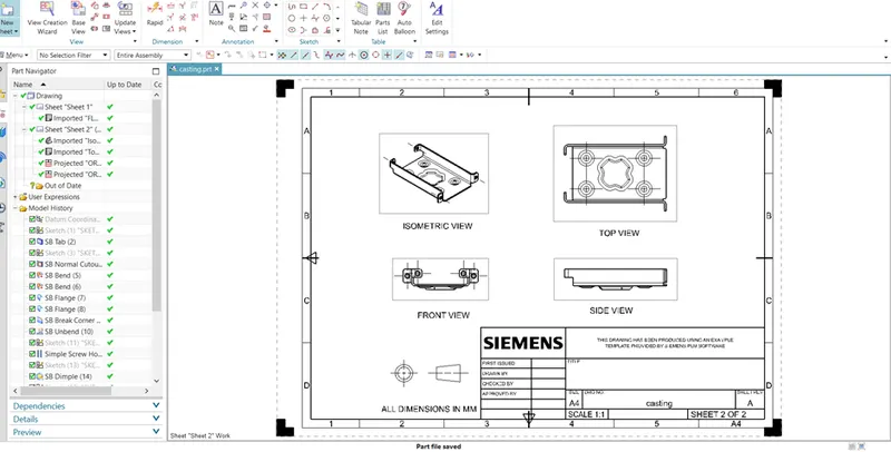
Creating the drafting views:
The drafting is used for to specify all the required information for the manufacturer to manufacture the part in the industry.
Conclusion:
In this challenge one can learn advanced commands that are used in NX software in sheet metal application.
This project also helps to understand why any operation is performed on the sheet metal.
I have created one casting as per the given guidelines and created drafting views for the sheet metal part.
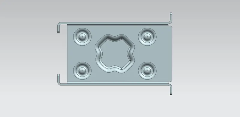
TOP VIEW
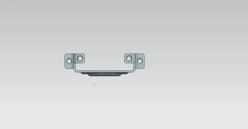
FRONT VIEW
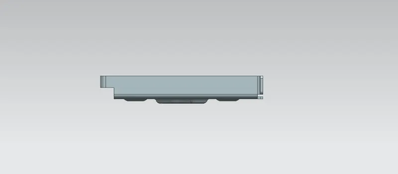
SIDE VIEW
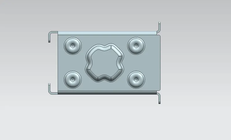
BOTTOM VIEW
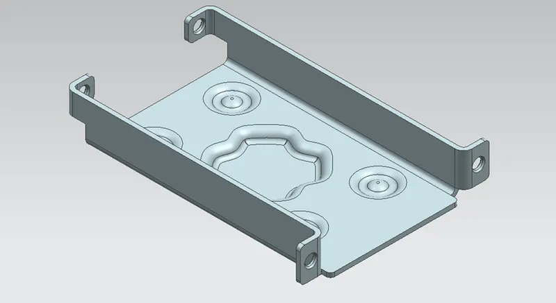
ISOMETRIC VIEW