Advanced Sheet Metal Design Using NX Cad Challenge_2_Box Assembly
Modelling of box Aseembly using NX CAD
Objective:
- To design 3D CAD model of box assembly using NX 12
Introduction:
- Sheet metal is metal formed by an industrial process into thin, flat pieces.
- Sheet metal is one of the fundamental forms used in metalworking, and it can be cut and bent into a variety of shapes.
- Countless everyday objects are fabricated from sheet metal.
In this project, the box assembly consists of 3 parts
- Box (Main Body)
- Lid
- Hinge
DESIGN METHODOLOGY:
- Box assembly is designed by keeping industrial procedure in mind to follow the design intent.
- The design methodology used for this project is summarized in below flowchart.
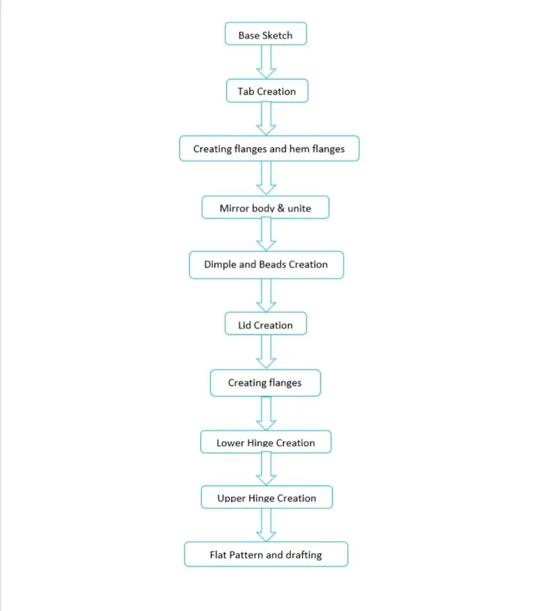
Design Requirements
Sheet Parameter = 200mm*150mm*1mm
List of Features used for designing the Casing:
Sketch
- It is a basic and initial operation for creating any kind of sheet metal components.
Tab
- It is a base feature that forms by extruding the sketch along a vector by providing thickness or adds material to a plane face.
Normal cutout
- It cuts the model perpendicular to the sketch.
Bend
- It modifies the del by bending the material on one side of a sketch line by adding a bend between two sides.
Flange
- It adds a flat flange on basis of edges at an angle to a planar face and adds bend between them.
Hem Flange
- It modifies the model by folding the edge of a sheet metal flange over onto itself for the purpose of safe handling or to increase edge stiffness.
Break corner
- It Rounds a sharp corner at edges
Unbend
- It flattens a bend and material adjacent to the bend.
Mirror
- It is used to create same features or sketches on basis of plane or sketch.
Hole
- It creates a whole on basis of circle created.
Dimple
- It lifts an area along the contour of a sketch that forms an stamping tool.
Bead
- It lifts a material along the contour of a sketch that forms an stamping tool.
Rebend
- It restores a bend
Unite
- Combine the volume of two or more solid bodies into a single body.
Flat pattern
- It creates a flattened pattern from the formed sheet metal part.
Procedure for designing Box Assembly :
- At first sketch is drawn by using rectangle for creating tab.
- Then flanges are added to edges that are parallel to each other.
- Another flange to these flanges is added on both sides.
- Closed contours are added to two flange edges.
- Flanges are added to edges of each flanges.
- Then Hem is added to these flange edges on both sides that looks like insert on another hem.
- Then whole part is selected to form on adjacent side by selecting proper plane as reference.
- Whole body is selected to apply unite that forms as single body.
- One of the faces is selected to sketch with proper geometry for applying dimple with required dimensions.
- By using mirror feature these dimples is selected to form on other face of body.
- Then unbend the total body and rebend to original position. Bead is added on surface of part.
- Above bead is selected for applying mirror Feature on basis of required plane for creating more beads.
- New datum plane is created for sketching bottom surface of box for making as closed box.
- Required flanges are added to close the part.
- Rectangle is drawn on surface for creating tab.
- Break corners are added to required edges.
- Another flange is added to these tabs with required dimensions.
- Hem flange with circular profiles are added to these flanges.
- Then unbend the tabs and flat pattern is applied to whole part.
- Required colors are added to all parts in a assembly.
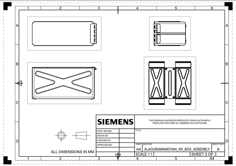
- New draft file is created for drawing these parts with required dimensions.
Different views of Casing :
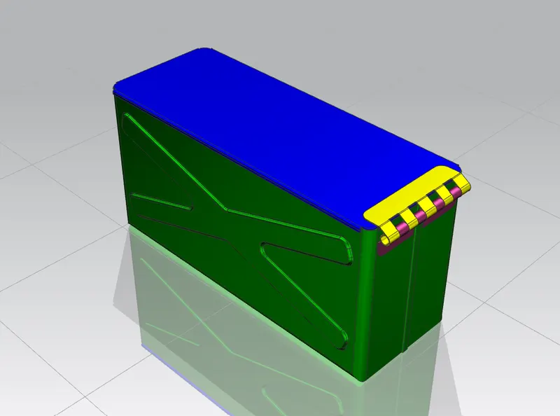
Isometric view:
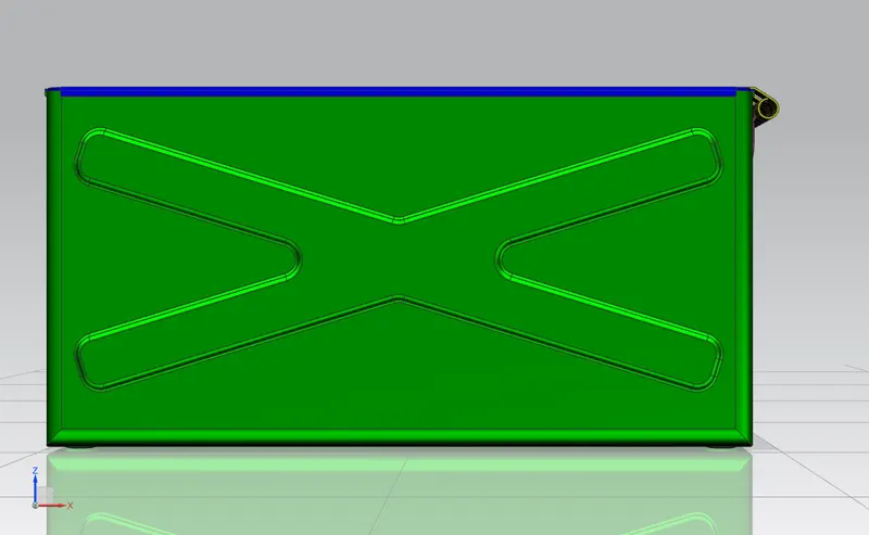
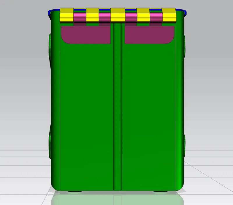
Front view:
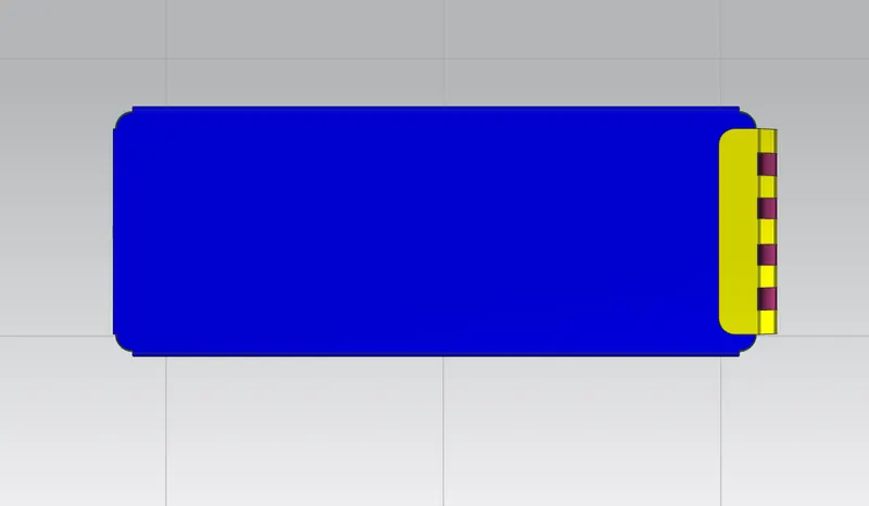
Top view:
Side view:
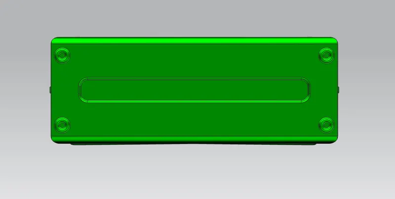
BOTTOM VIEW
DRAWING SHEET :
MODEL FILE LINK :
https://drive.google.com/drive/folders/17MA2W1gA7apReVEWLWZusXoMb1-eJVWp?usp=sharing
Conclusion
- Thus, the designing of Box Assembly by using NX-Cad applications has been created.