Advanced Sheet Metal Design Using NX Cad Challenge_1_Casing Design
TITLE OF THE OBJECT : Casing-Design using NX CAD Sheet Metal .
OBJECTIVE : Developement of casing sheet metal component with in design standards.
INTRODUCTION : Siemens NX CAD software designed for the efficient creation, modification, and validation of sheet metal components. It is particularly well-suited for industries like automotive, aerospace, and industrial equipment manufacturing, where sheet metal plays a significant role in product design. NX offers high-performance modeling, drafting and assembly design- powered by Synchronous Technology -that can’t be beat. The product design tools, as well as potential data management capabilities, make this a complete solution, from design to production. It allows detailed control over bends, flanges, and forming features, which is essential for industries with stringent design requirements. NX integrates design and manufacturing processes within one system, reducing time to market and improving accuracy.
DESIGN METHODOLOGY :
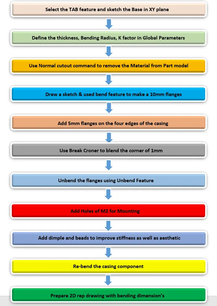
DESCRIPTION :
Design and development stages of Casing component.
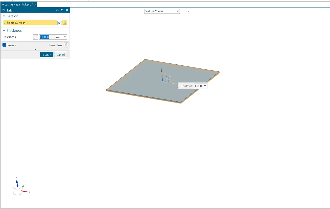
- TAB : Tab feature is a fundamental tool used to create the base geometry for a sheet metal part. It allows users to create a flat, planar piece of sheet metal, which can then be used as the starting point for additional features like flanges, bends, and cutouts. In NX it is denoted as Tab, PAD in catia and Base flange in solidworks.
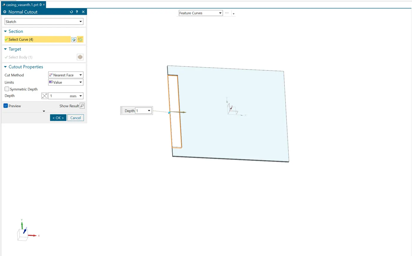
- NORMAL CUTOUT : Draw the profile which is to be cutdown on the base flanges and.
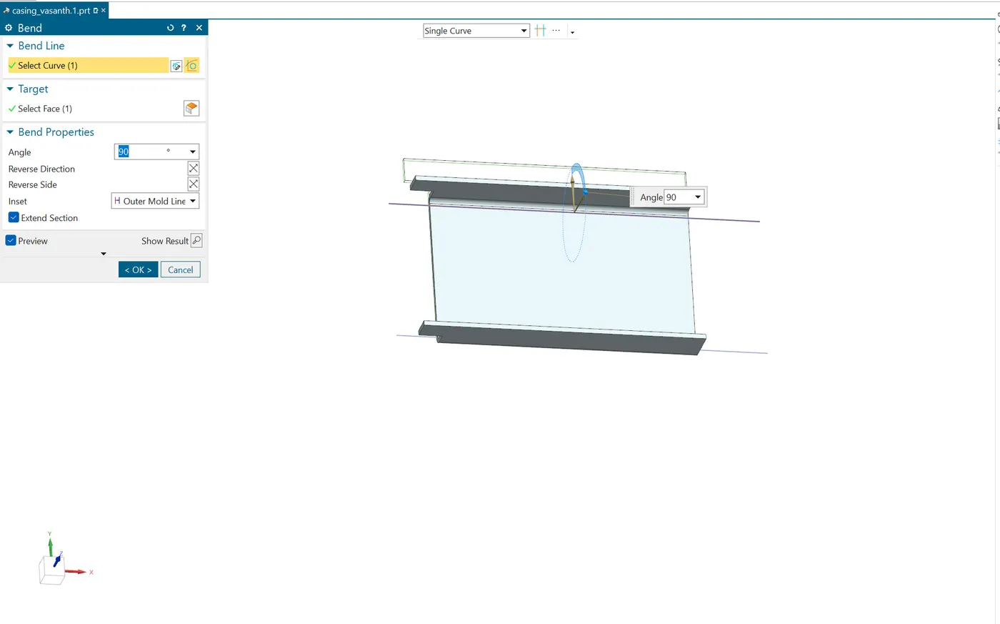
- BEND : Draw the sketches on the base flange surface and define the dimension of an flanges and use the bend command to bend at an 90 deg angle.
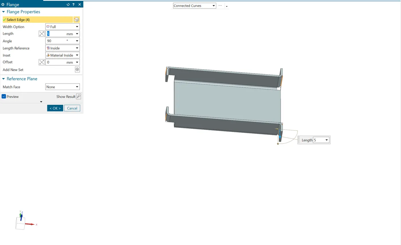
- FLANGES : Flanges are created at the edge of an Base flanges. The flange shape is controlled by edit sketch in the feature property.
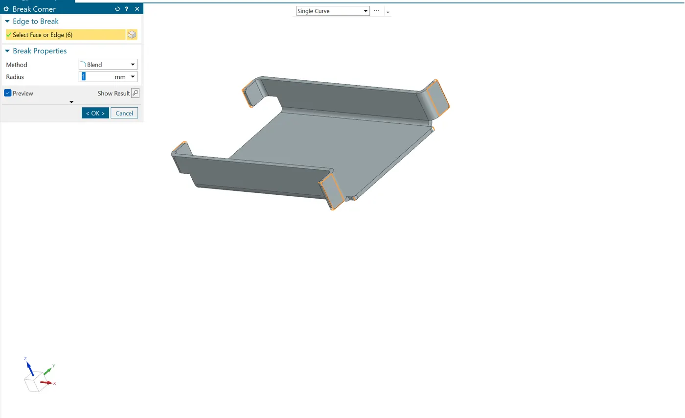
- BREAK CORNER : This feature is used to add the fillets on the corner's of the flanges. It is a good tool to practice to distribute the stress concentration and it will reduce the risk of handling in the shop floor.
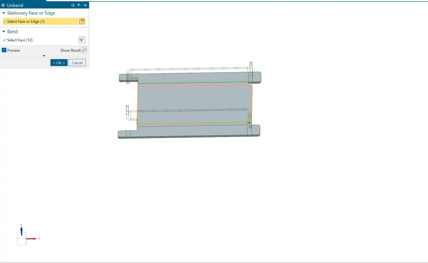
UNBEND : Unbend can be done and sketches are drawn to make an cutout in the bended area. In sometimes it is used to view the flatten .
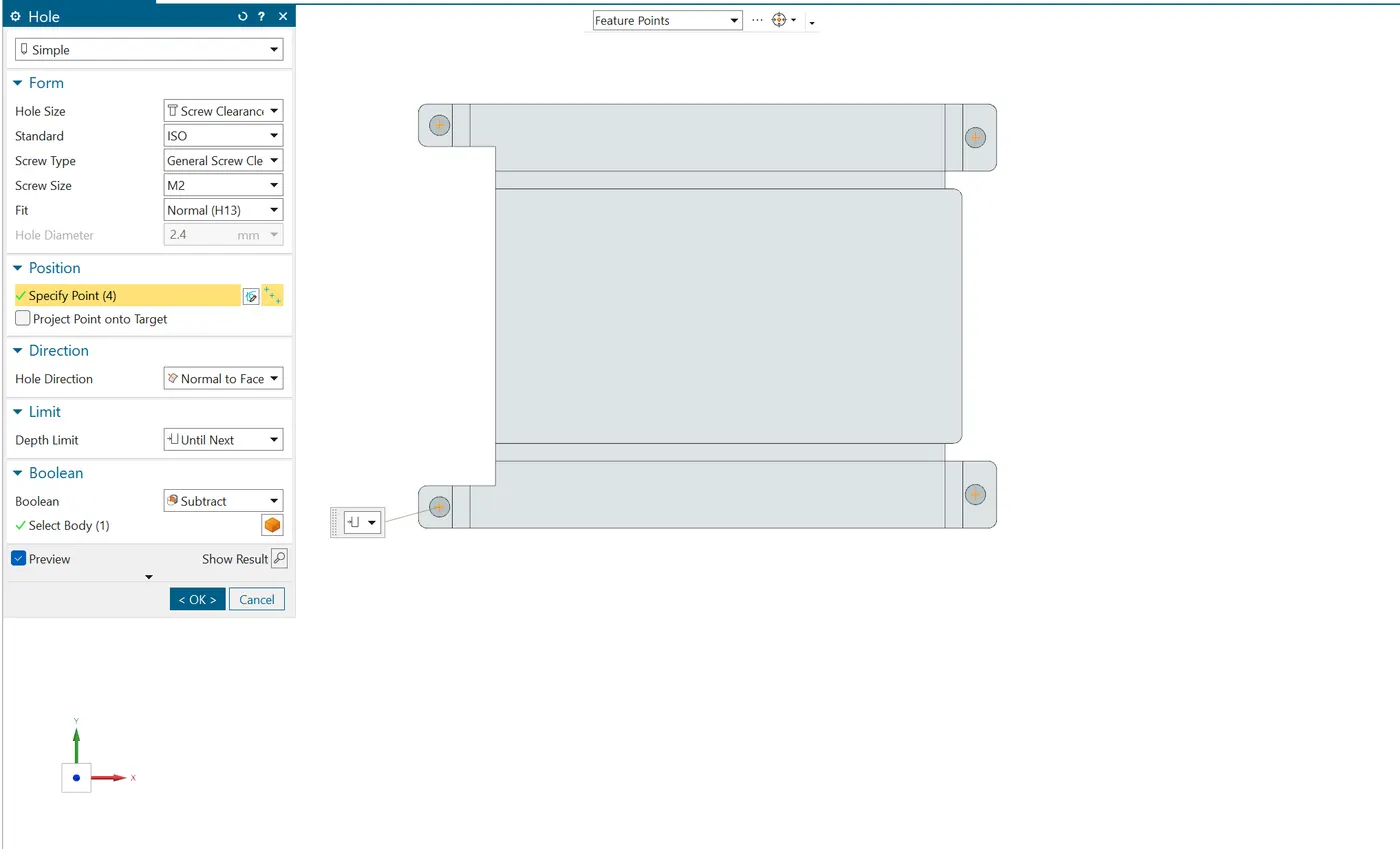
- HOLES : Holes are used for mounting purpose , it is very handy feature to make a quick cutout with threads standards.
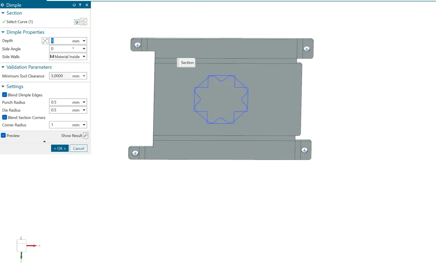
- DIMPLE : Dimple is act as a reinforcement without adding any addtional parts , Sometimes it is used to increase the aesthethic by adding LOGO onto it . This is done by Stamping process.
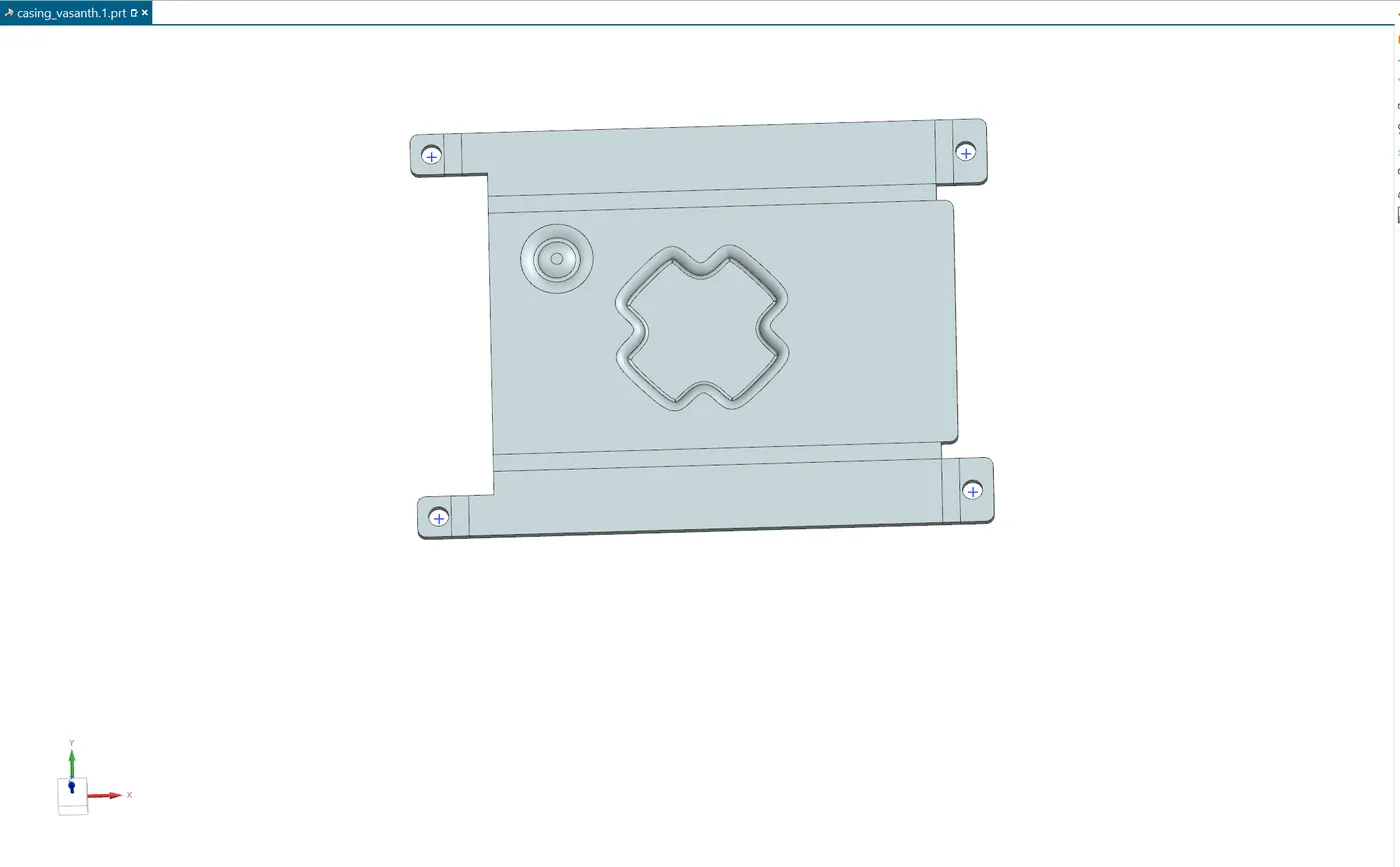
- BEADS : It mainly used to increase the rigidity of an part, it is aslo know as Embossess.
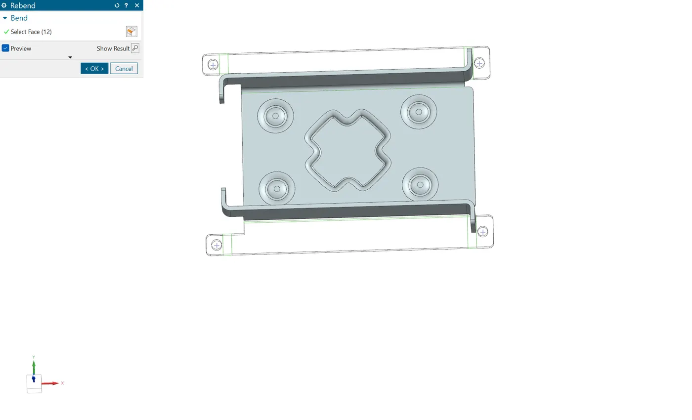
- RE-BEND : Rebend is used to move the flanges to its original position.
- FLAT PATTERN : It shows the exact shape, dimensions, and layout of the sheet metal part before it is bent or formed into its final 3D shape.
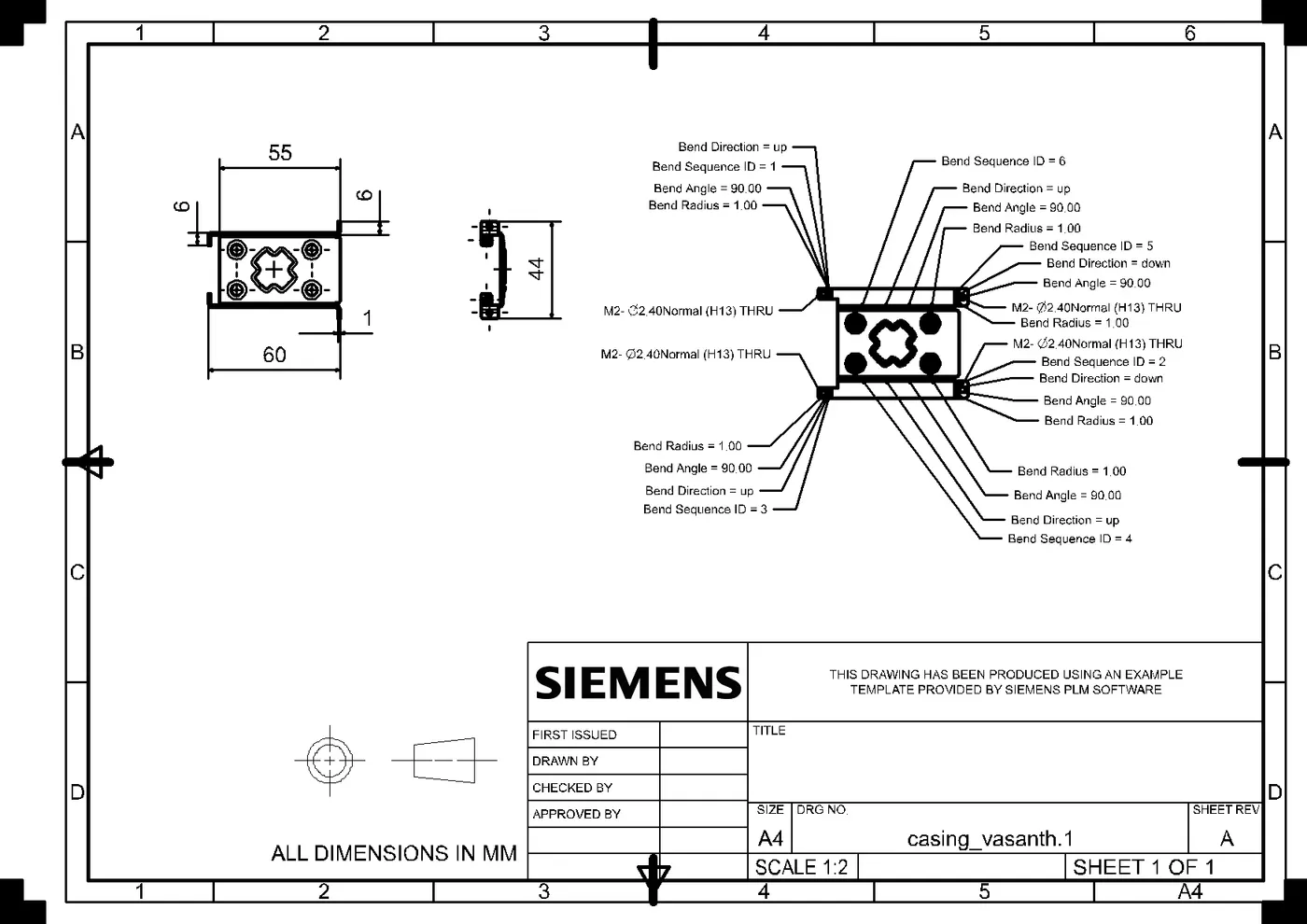
- DRAFTING : It is a 2D representation of an 3D shape this can be necessarily prepared before he Manufacturing process. it has contains the additional details about the bending dimension and angle .
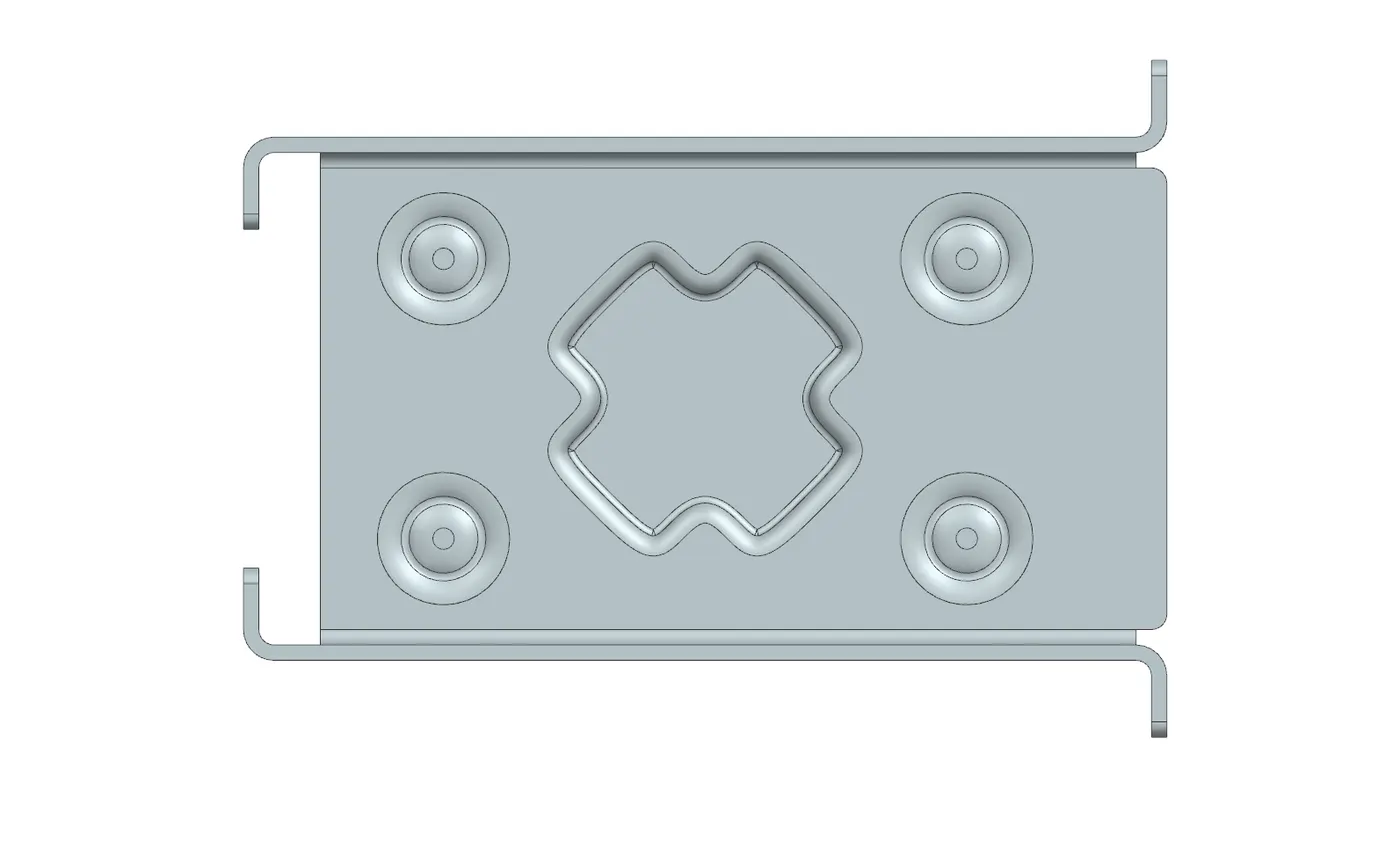
TOP VIEW :
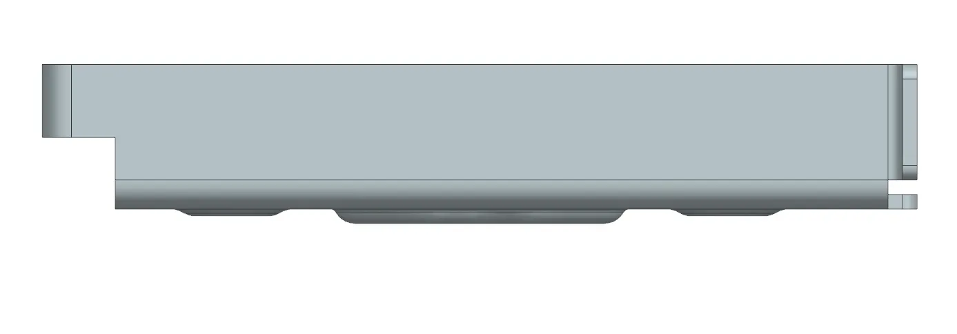
SIDE VIEW :
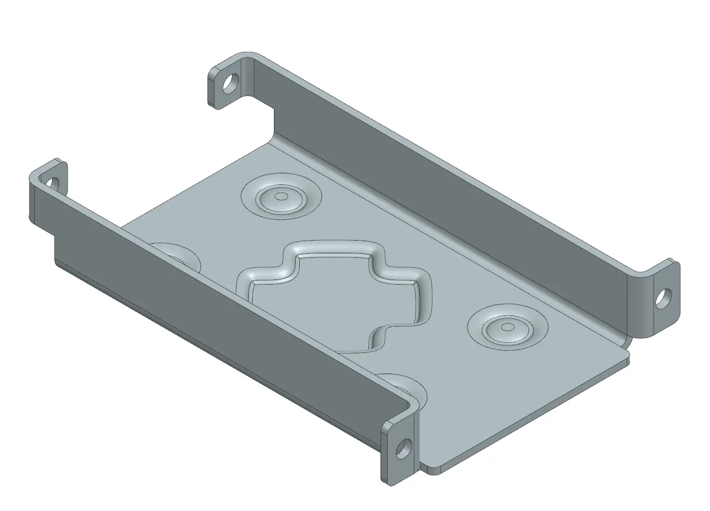
ISOMETRIC VIEW :
CONCLUSION :
In this project, I have used the features like Tab, flnages, Normal cutout, break corner etc. Developed the casing model with in sheet metal design standards.