Advanced Sheet Metal Design Using NX Cad Challenge_1_Casing Design
CASING
OBJECTIVE:
Learn to design a sheet metal casing in industrial manner by using Siemens NX.
INTRODUCTION:
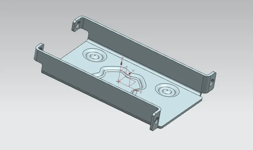
Sheet metal parts are widely used in machinery, enclosure, brackets, and automobile due to its various advantages. The parts are normally manufactured with break press. Sheet metal is nothing but the thin sheets made from metal of size ranging from 0.5 to 6mm. In this project I used NX CAD tool for designing the sheet metal bracket. NX CAD is used as design tool in more than 85% of the sheet metal industries.
DESIGN METHODOLOGY:
simple and easy design methodology is followed during this project; only thing is that we have to just keep an eye on order of unbending and rebending the casing. The design methodology used for this project is summarized in below flowchart.
DESCRIPTION:
Sketch:
For creating any sheet metal surface, we have to first make a sketch. So, I started with creating simple rectangular base sketch for creating the tab. Other than tab, various sketches are also made on different planes or faces for creating other different part during designing.
Tab:
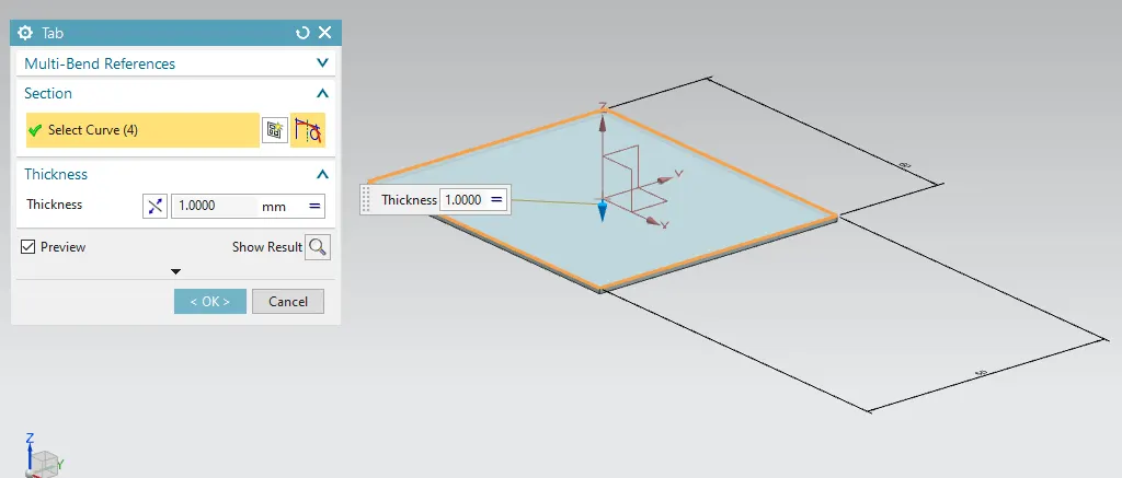
Tab is the first parent feature in sheet metal designing using Siemens NX tool. All the other feature are usually based on tab. In this casing design, I created the tab by using the sketch on XY plane having defamations of 50*60.
- Normal cutout:
- This feature is used to cut the portions of the sheet metal by assigning sketch curves.
Bend:
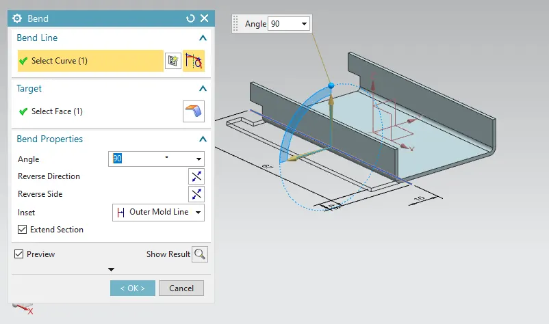
Bend means modifying the model by bending material on one side of the sketch line. Bend feature is used to bend the sheet metal component to any angle. A base sketch is also required for creating the bend in sheet metal part. For this casing design I used sketch including two symmetric straight lines with respect to X-axis as a bending curve.
Flange:
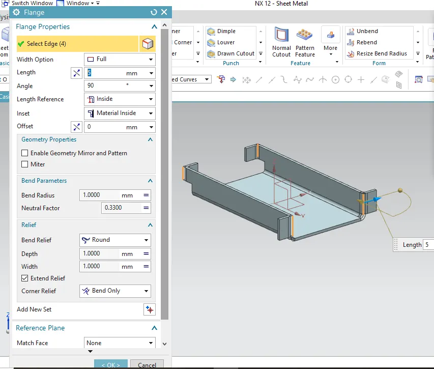
Flange is used to add extra material to the existing edge at any angle and of any size. For this project of casing design, I added four flanges on different edges. I used full flange having parameters of 5 mm length with material inside the reference edge.
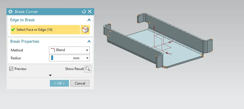
Break Corner:
Break corner feature is used to smoothen or chamfer the sharp edges of the sheet metal part. This action helps to prevent the stress concentration and fracture breaking. For this casing design I used blend with 1mm.
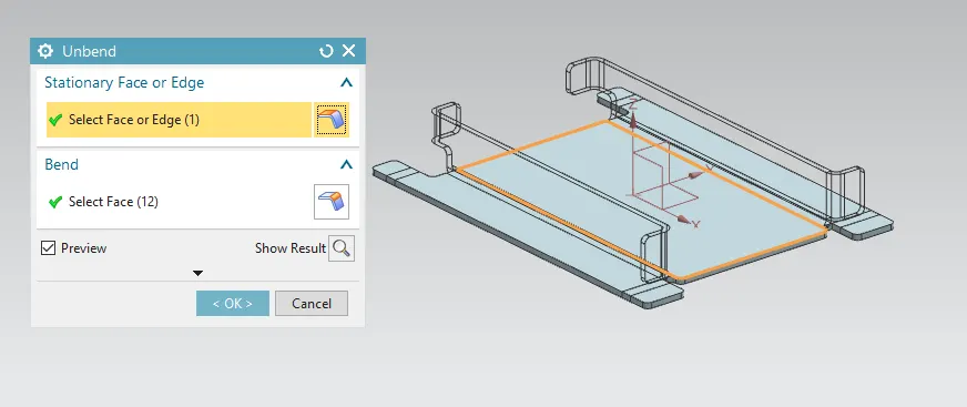
Unbend:
Unbend feature is one of the most powerful feature in NX. In industry we have to mark all the marking and sketch on flat sheet metal before it went to actual operations, so this unbend feature allow us to do that activity in Siemens NX software. For this project of casing design, I used this feature by selecting the tab as stationary face.
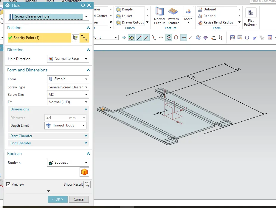
Hole:
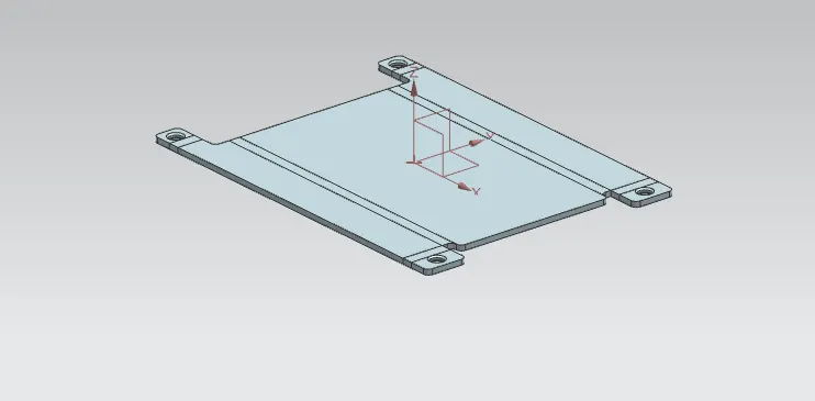
Hole feature is used to generate hole with definite parameter on sheet metal in Siemens NX. We can create different types of holes using this feature, in this project I mainly used simple screw clearance hole. I first sketched four symmetric points with reference to the X-axis and then hole feature is applied to all four points.
Dimple:
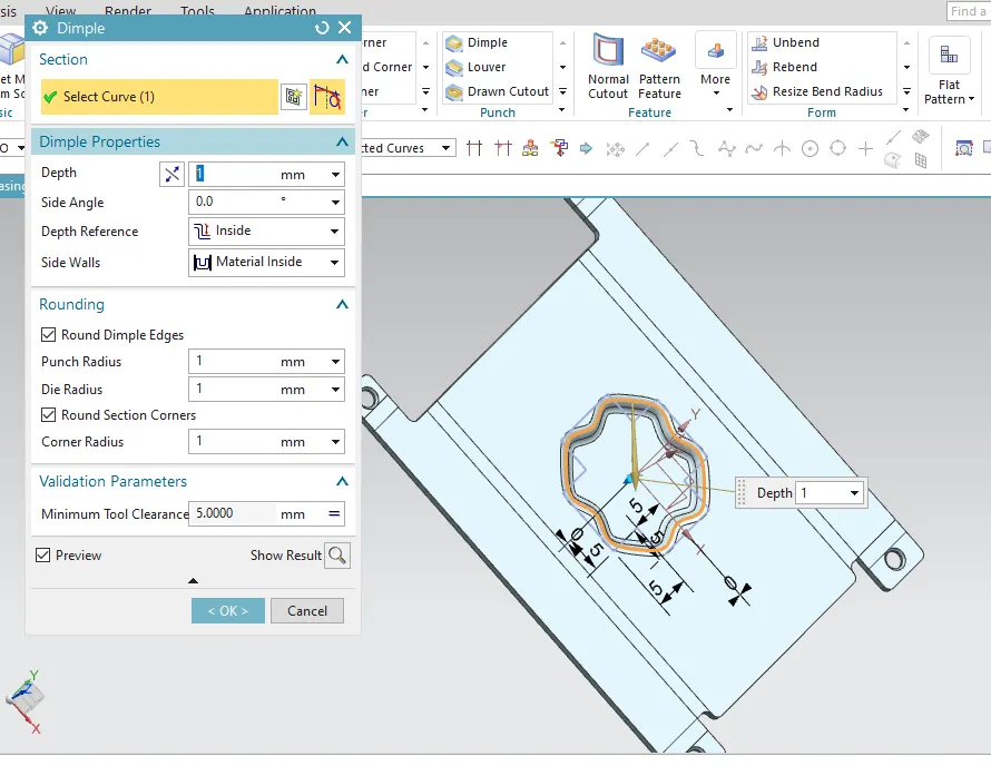
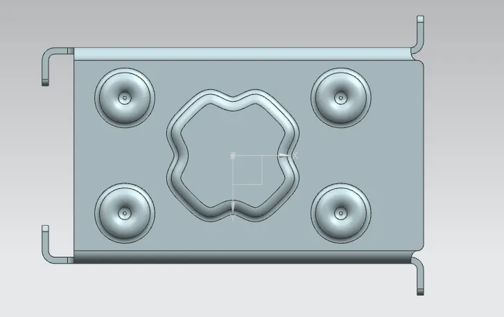
Dimple is the feature that lifts the area of model inside the sketch that simulates a stamping tool. Generally, it helps to strengthen the flat structure. For this casing design I first created a sketch using straight lines then I used studio spline function to convert the straight lines into the 16 points end to end connected curve. After that I use dimple feature to create the final dimple.
Beads:
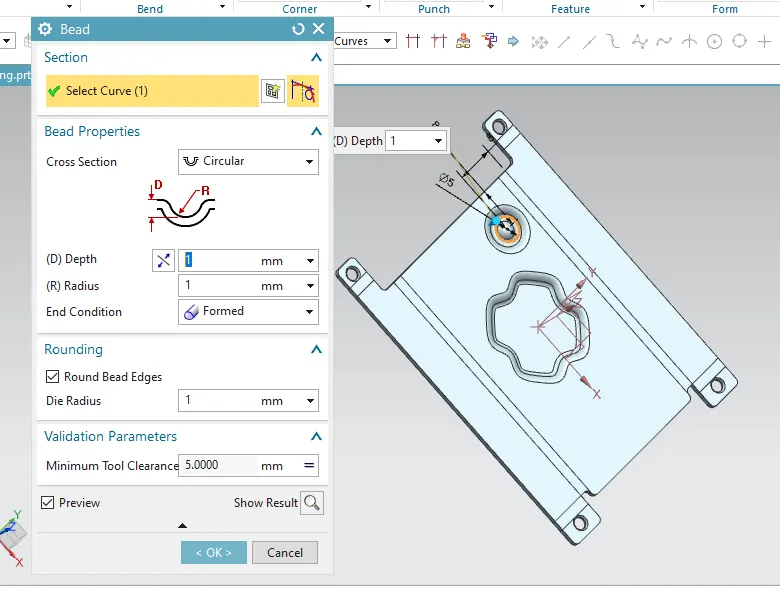
Bead is similar feature like dimple the only difference is that by using dimple we lift an area while in bead we lift the contour of the sketch. It also added to strengthen the component. For this project, four small beads are applied in the symmetric position as shown in the image below.
Rebend:
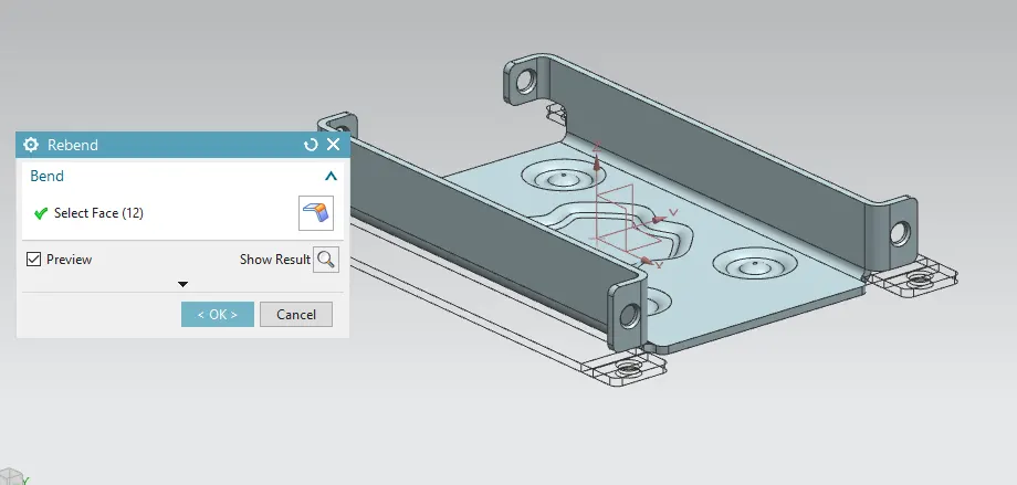
Rebend feature is used to restore the unbend feature to its previous bent state along with any features added after the unbend feature. This is done by using rebend feature and selecting all the bends carefully in order they unbended.
Flat Pattern:
Flat pattern feature allows us to covert 3D sheet metal component into 2D form in Siemens NX software. By using this flat pattern feature we can easily avoid error like interference or collision.
Drafting:
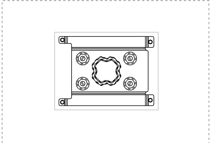
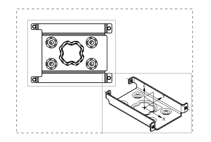
After designing 3-d model for further process of manufacturing we have to convert the entire sheet metal component into 2D form for easy interpretation. For this project of casing design a drawing is created out of the flat pattern in 2:1 scale in A4 size.
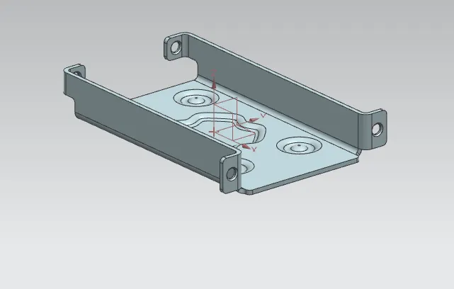
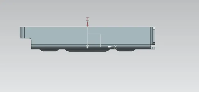
Different views of Casing:
Isometric View:
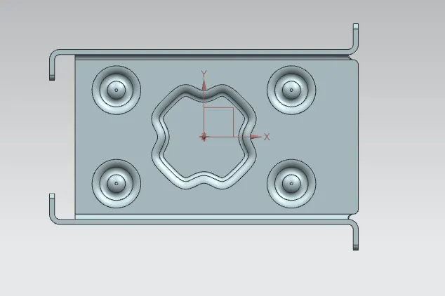
Top View:
Side view:
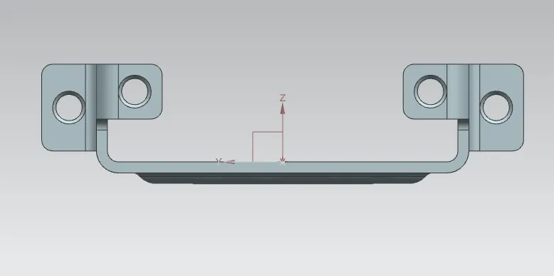
Front View:
Bottom view:
CONCLUSION:
- Successfully learn to design a sheet metal casing in industrial manner by using Siemens NX.
- Become comfortable of using Siemens NX environment.