Advanced Sheet Metal Design Using NX Cad Challenge_1_Casing Design
week-1 challenge:
Advanced sheet metal design using a nx cad:
casing box:
OBJECTIVE:
to create a sheet metal product using a NX cad.
by using a tab, normal cutout, flange,bend, hole and drawn cutout commands are used to create a product.
INTRODUCTION:
sheet metal:
sheet metal is the metal part which has the thickness less than the .25inch(6mm).
this materials commonly used was stainless steel, aluminium, copper and mild steel etc.
appilcation of sheet metal in household components, electrical components and more.
NX Cad:
siemen Nx Cad is the software used to create a part model, drafting and sheet metal products.
it is also called as "unigraphics" initially.
it is the most commonly used industrial software.
Design Methodology:
Description:
command used:
*Tab, *Normal cutout, *flange, *bend, *dimple, *drawn cutout .
Tab:
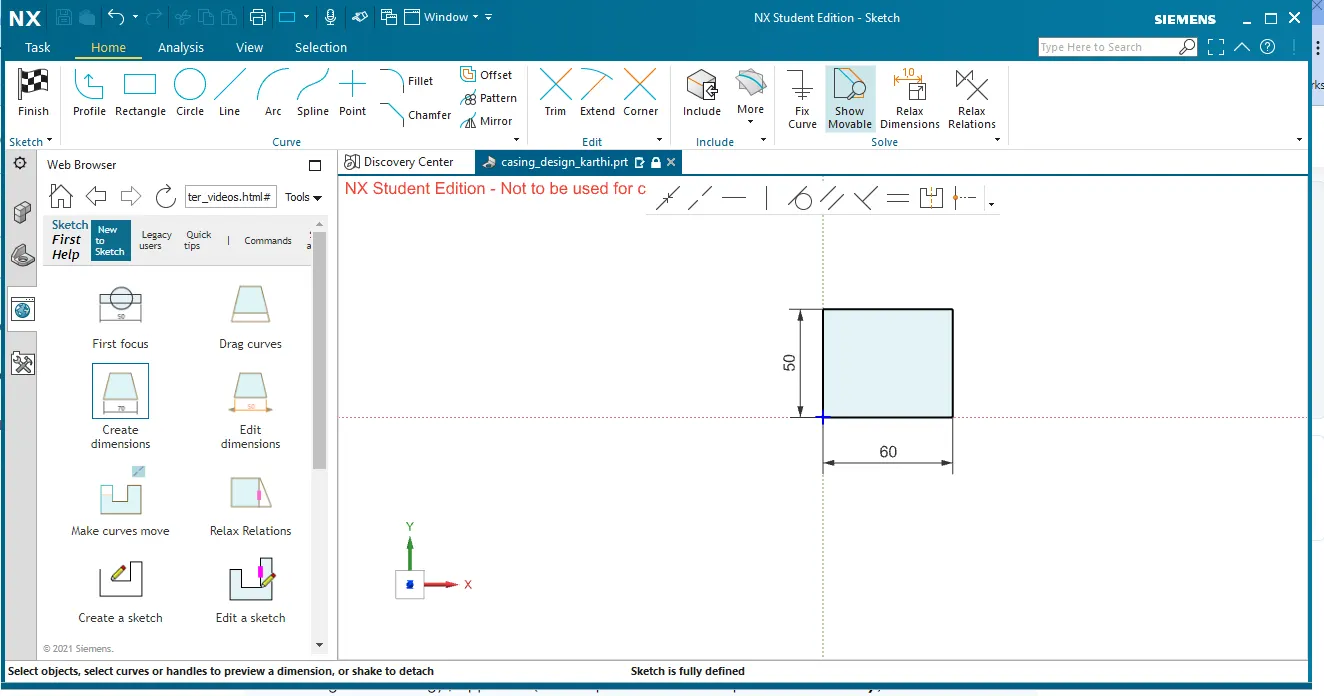
first, the tab is created with a dimension of 50*60mm dimension with the thickness of 1mm.
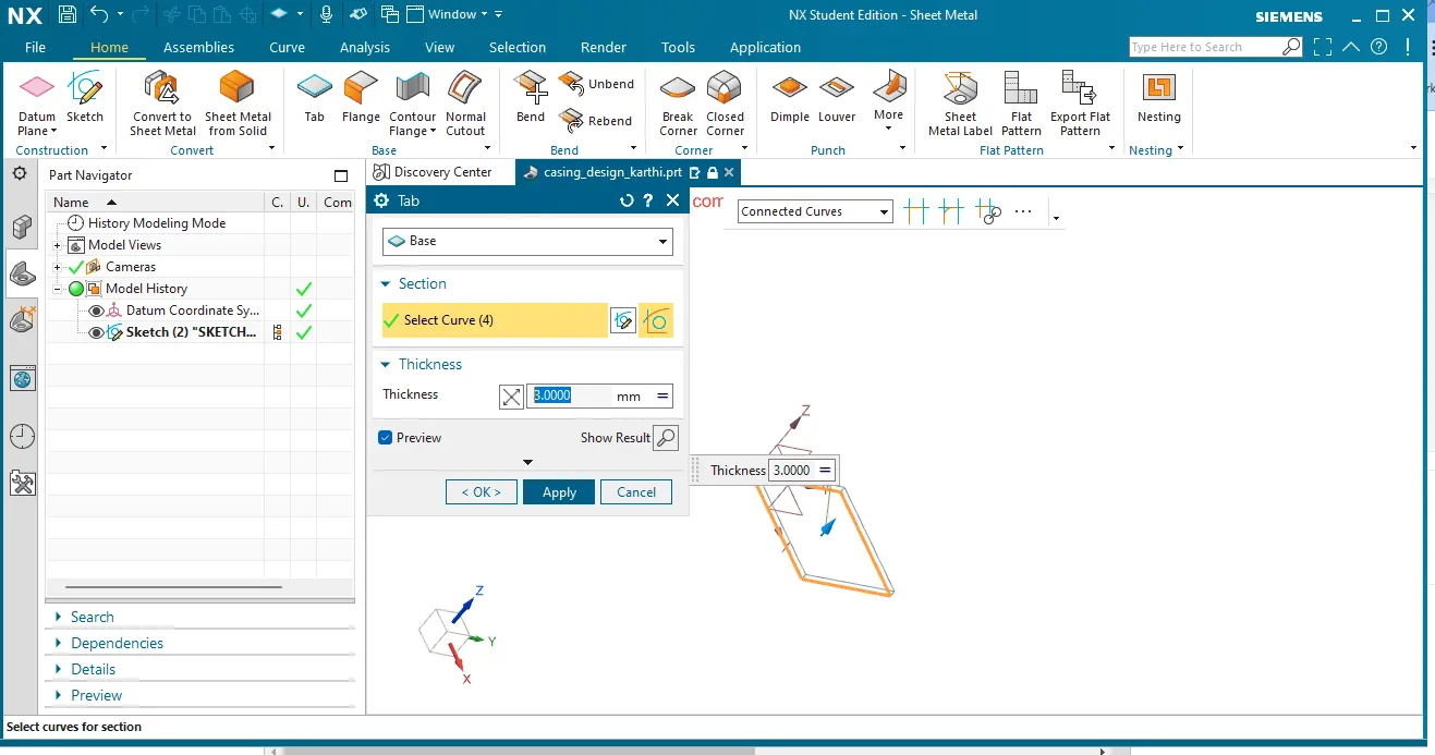
for this click on Tab icon. in select sketch, draw the sketch and finish it.
then provide the tab thickness as 1mm.
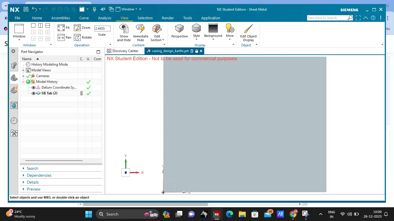
here, the tab is created.
normal cutout:
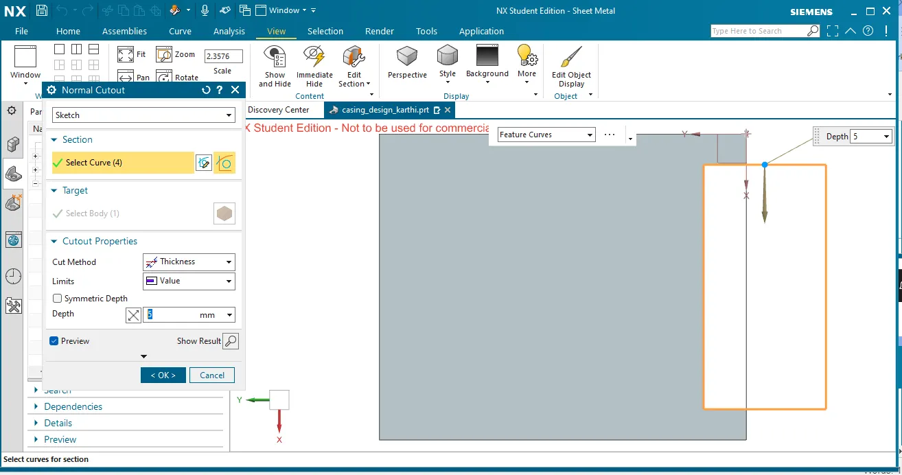
by using this command the cutout of the sketch is provided to the sheet metal component.
first, the sketch is provided. then the cutout of the sketch with respect to the part.
this is shown in the below.
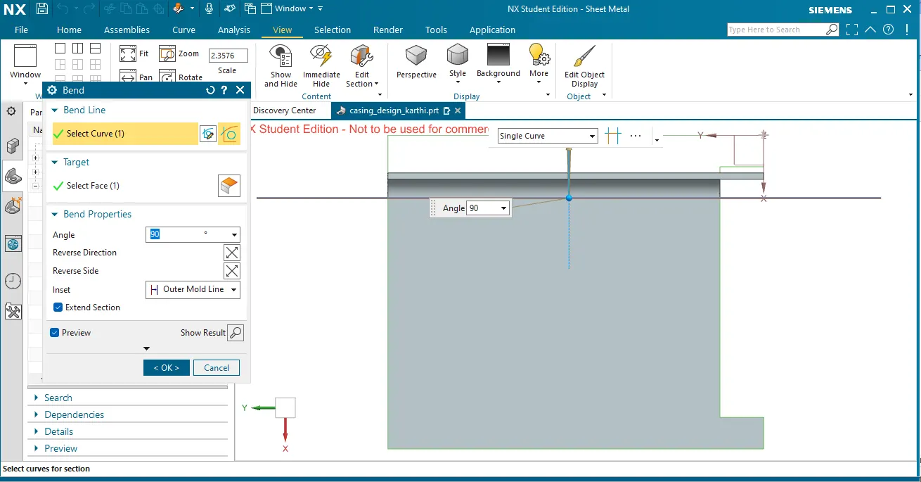
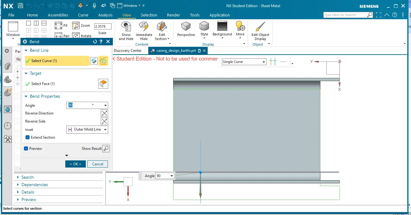
bend:
bend command is used to bend the part at an required angle and for an required length.
the sketch used for the bend is a straight line which is extended beyond the part.
then the bend is occur with the property of material with neutal axis.
the below shows the bend in NX cad.
flange:
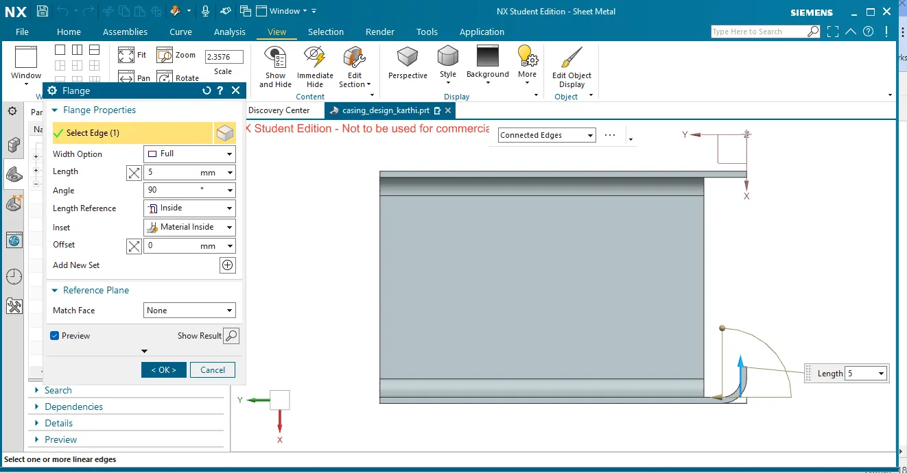
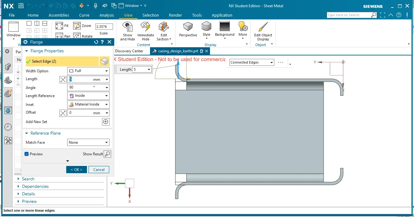
flange is similar like a bend, the differnece is here , the sketch is not provided.
to create a flange select the edge of the part and provide the angle, length of the flange.
for this challenge, four flanges are created at the four edges.
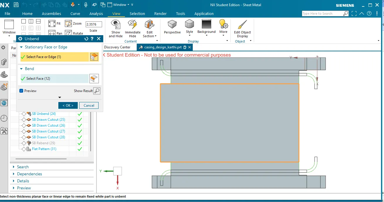
unbend:
unbend command is used stretch the part along the flat plates.
the sheet metal component is flatten and provide the size of the sheet metal blank.
here it shows the unbend command.
holes:
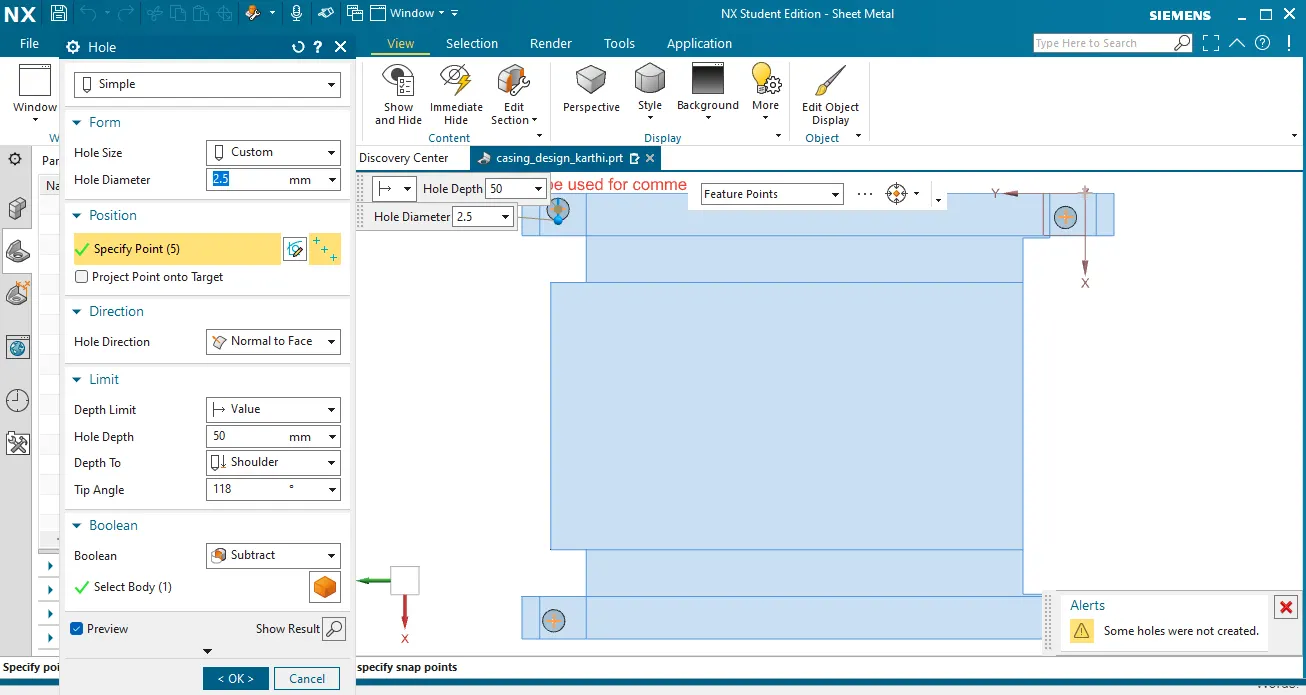
hole command is uesd to create a hole on the sheet metal.
for this a point a neede to create a hole.
then after creating a point, then provide a hole diameter in mm.
depth, tip angle etc.
dimple:
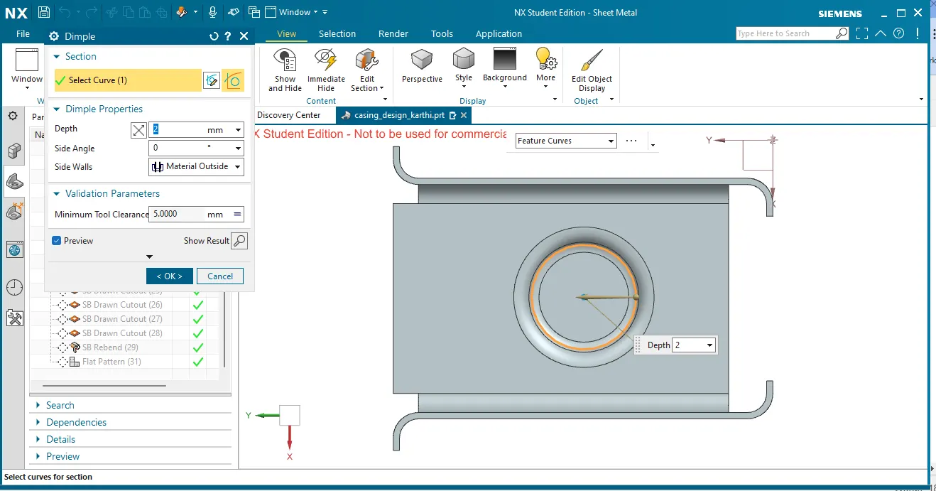
dimple is used to lift an area inside of the model. which stimulate the stamping tool.
for this challenge acircle is created. then lifted to the bottom sidefor about 2mm.
the stamping tool is used to create a dimple in the industry.
Drawn cutout:
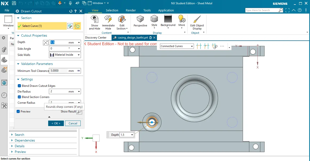
drawn cutout is used to provide a cutout which uses the stamping tool with the cutout section.
first, create a sketch and use the drawn cutout to provide both stamp and a cutout.
below shows the drawn cutout used for this challenge.
for selecting a sketch individual closed surfaces are only selected. not a bunch of closed curves selected, it shows an error.
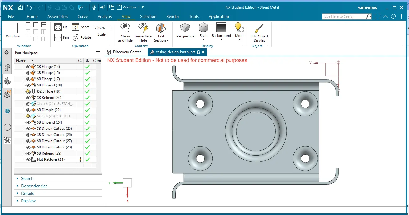
final view of the casing design is shown below.
flat pattern:
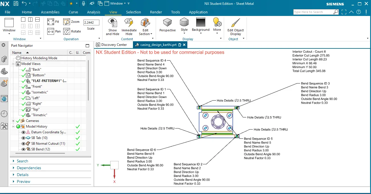
by using a flat pattern.the flat shape of the component is obtained.
it also shows what are all the operation is to be done on the sheet metal blank to obtained the final shape of the component.
here, below shows the falt pattern with the bend, hole, cutout etc.
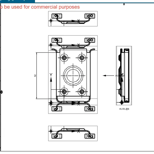
drawing of the component:
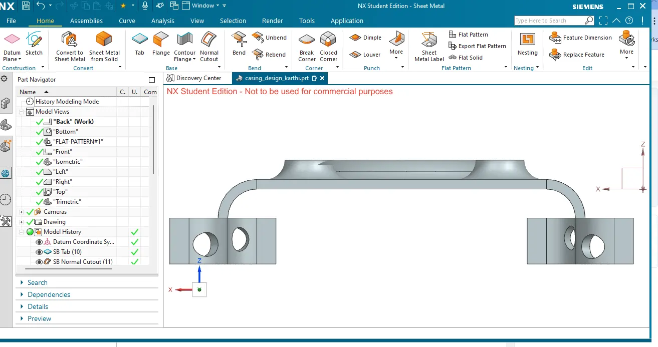
All views:
front view:
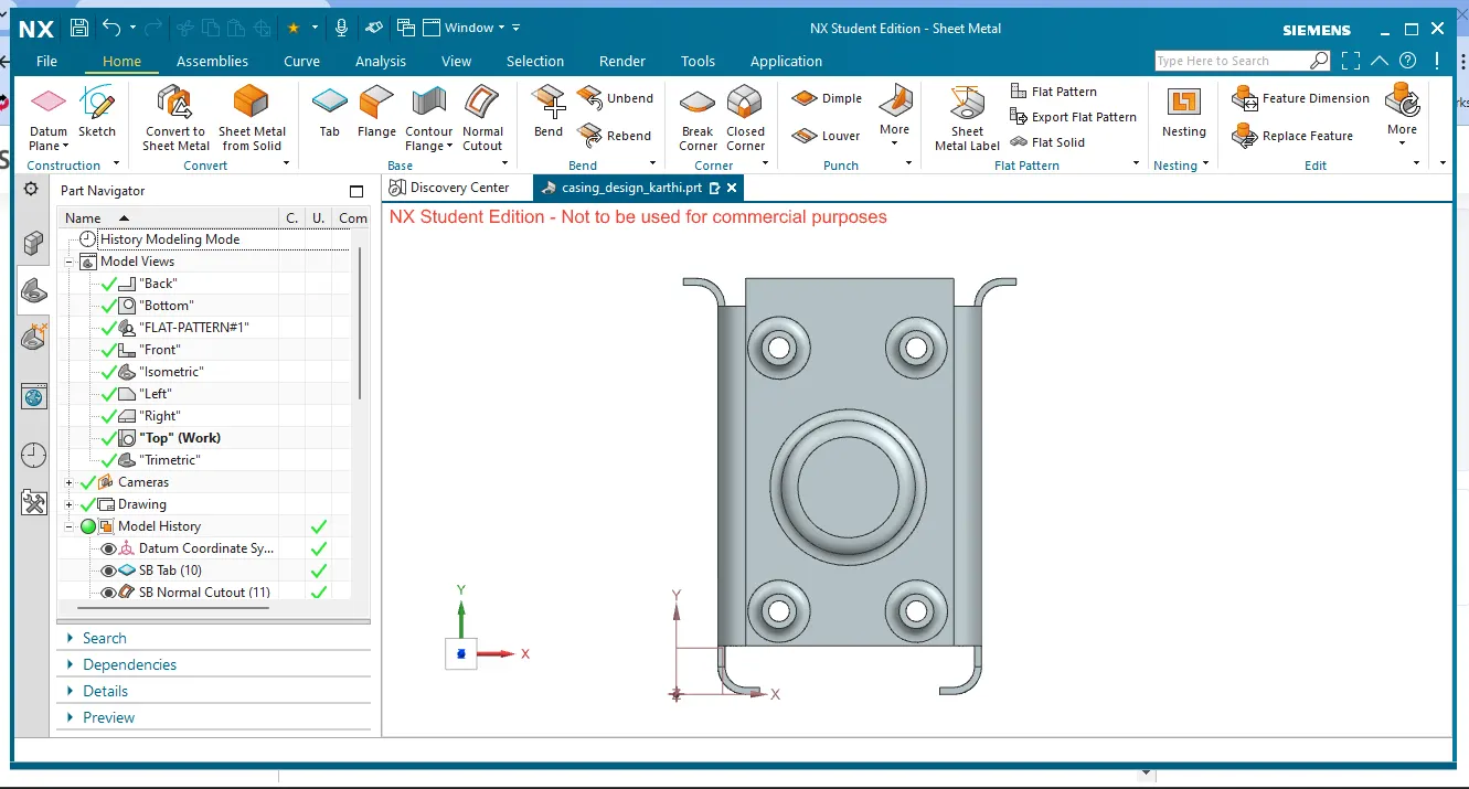
top view:
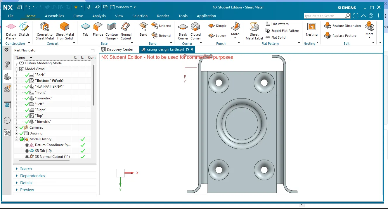
bottom view:
trimetric view: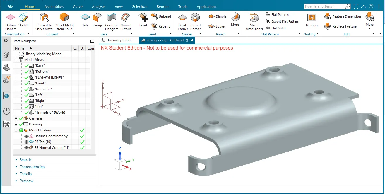
isometric view:
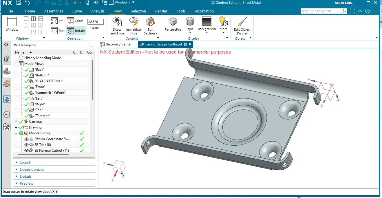
conclusion:
. hera a detailed report on Sheet Metal Component with good explanation on Sheet Metal modelling tools applied throughout the modelling of Sheet Metal Casing is done.
the part file is attached below.
===================================================================================================================