Advanced Sheet Metal Design Using NX Cad Challenge_1_Casing Design
Advanced Sheet Metal Design using NX CAD Challenge #1 - Casign Design
Objective -
To design a Sheet-Metal Casing, as per the instructions provided in the PDF file using NX-CAD software. And also create a detailed drawing of the completed product.
Introduction -
Siemens NX provides a set of tools within the it that allows for simple and fast design of sheet metal parts, helps determine their material and manufacturing process. Siemens NX software incorporates material and process information in sheet metal-specific modelling features: bends, flanges, tabs, cutouts, beads, dimples, louvers, corner and edge treatments, patterns and other features.
Its also allows to quickly convert solid models to sheet metal components, and create sheet metal parts that enclose other components. All the NX Sheet Metal-specific features enhances the design procedure and productivity. All common dimensions can be set as default for ease of work. Sheet Metal products are used in almost all industries, thus design of needed components are made easier with CAD softwares such as Siemens NX.
Design Methodology -
- Select a new Model in NX CAD with a suitable name and enter the Sheet-Metal workbench.
- Create a sketch on XY Plane with 60X50 mm dimension
- Set default values in Menu>Preference>Sheet metal.
- Follow the instruction in the PDF to form the Base feature’s profile.
- Apply Bends on the Base feature.
- Use Break Corner command to round the sharp corners.
- Unbend the sheet metal product
- Add size M2 holes on the middle of the flanges.
- Add the Dimple and Beads on the body using sketches as reference
- Re-Bend the Metal Sheet.
- Create the Drafting of the product in a new Drawing.
Descriptions -
The important tools used in the design procedures are -
- Sketch
Helps to draw profiles for the different tools to used on.
Studio Splinecreates a spline through all selected points.
Move Curve can move a created curve according to selected references by provided given distance/angle.
Mirror Curve mirrors the drawing in the sketch with respect to an axis/plane. - Tab
Creates a base feature by extruding a sketch along a vector. The thickness and material data can be provided. - Normal Cutout
Cuts the base feature/part perpendicularly with reference to a sketch/profile provided. - Bend
Modifies the base by bending it with a reference flat surface and a sketch line to depict the bend. - Flange
Adds flanges to the edges selected. Angle between main surface and length of the flange can be provided. - Break Corner
Smoothens all selected sharp corners. It fillets the corners with the provided radius. - Unbend
Flattens the created 3D sheet metal part into a 2D part. - Hole
Used to create specific types of holes for screws. The threading, boring, etc can be provided separately. - Dimple
Lifts/ creates a depression on the material along a sketch. It stimulates stamping process. - Bead
Lifts the material along a sketch, this also stimulates a stamping operation. - RebendRestores the bends on the selected faces of the created feature.
- Flat Pattern
Creates a flat pattern of the feature with all the information on the dimensions. - Drawing
It’s used to create drafted drawings of selected part/product.
Base Viewcreates the main view on the drawing sheet.
View Creation Wizard helps to create customized view of the selected product.
Product Images -
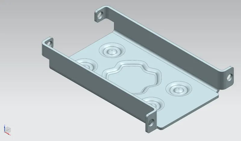
Isometric View :
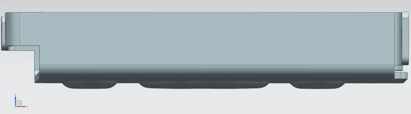
Front View :
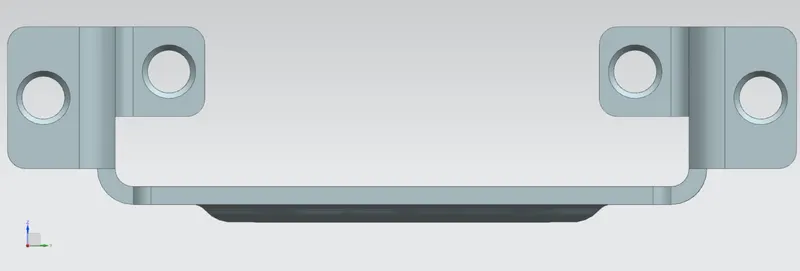
Side View (Right) :
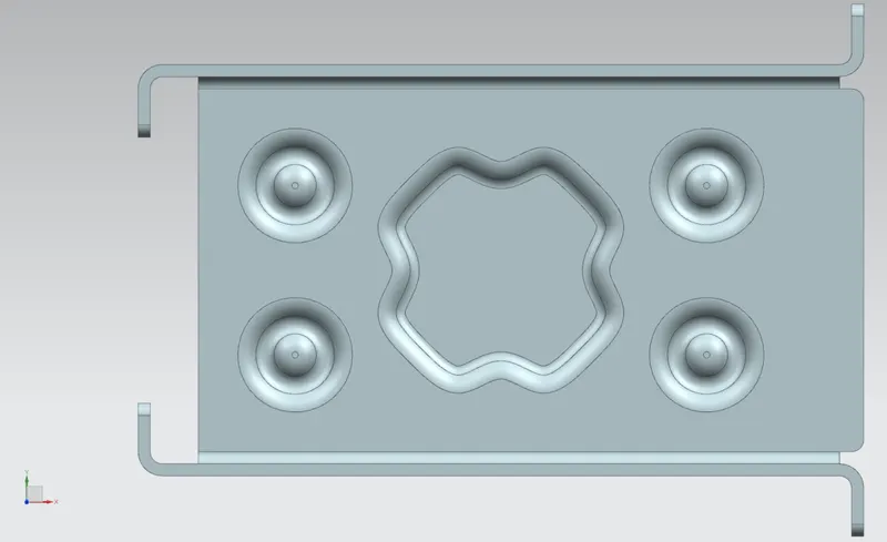
Top View :
Detailed Drawing -
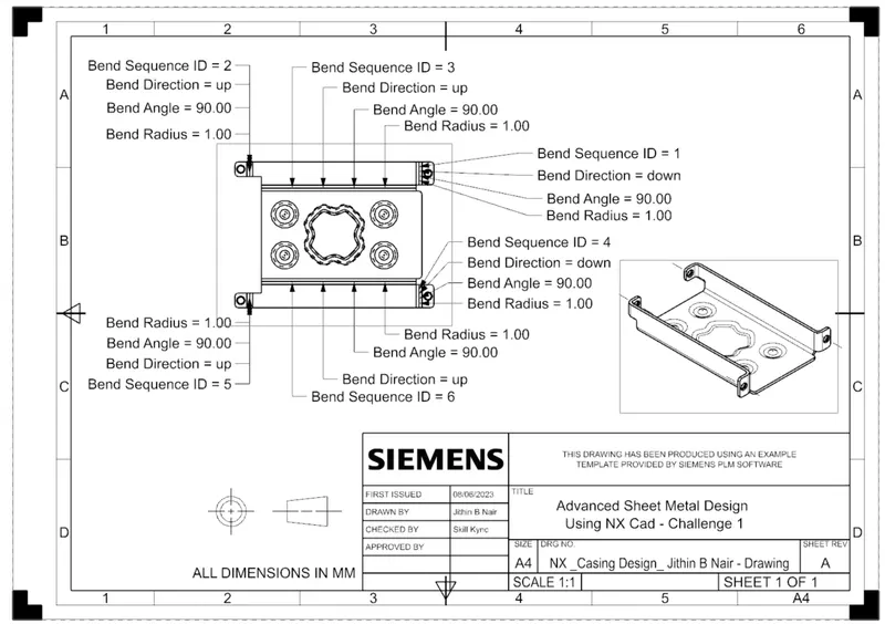
Conclusion -
The Sheet Metal Casing is Designed using Siemens NX CAD software and the drawing of the product is made.