Advanced Sheet Metal Design Using NX Cad Challenge_1_Casing Design
Write a detailed report on Sheet Metal Component with good explanation on Sheet Metal modelling tools applied throughout the modelling. Also attach the Final model Images (Min. 4 images) of Sheet Metal Casing.
Link for PDF.
https://drive.google.com/open?id=1iFGcicuUq7InjqHUS9Eub5QXL7nwYrOy
This project can be published in the Project site.
Points to be followed in report
- Title of the Project
- Objective
- Introduction
- Design methodology / approach (To be explained with the help of Flowcharts only)
- Description (Need to explain tools/ Features used while designing)
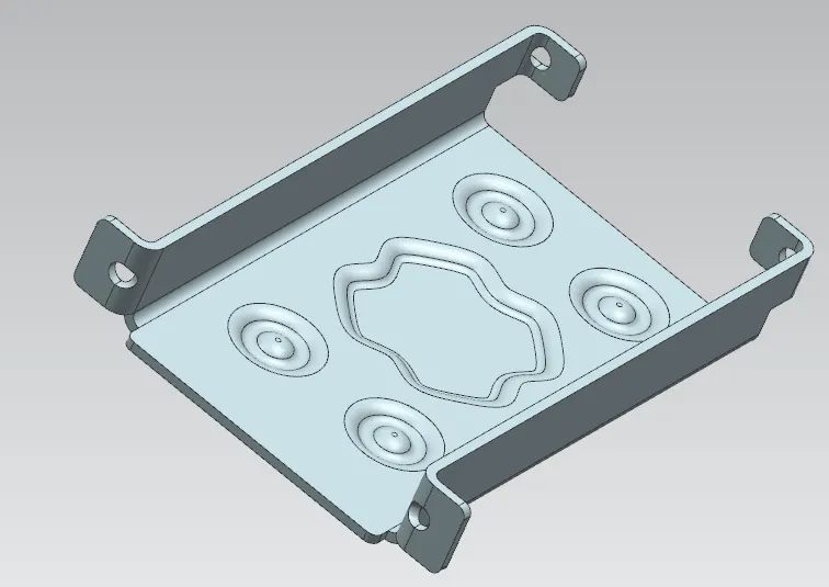
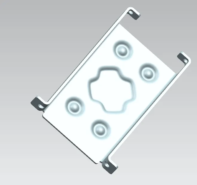
- Upload a min of four screenshots of Model in the report. (Front View, Side View, Isometric View and the Top View)
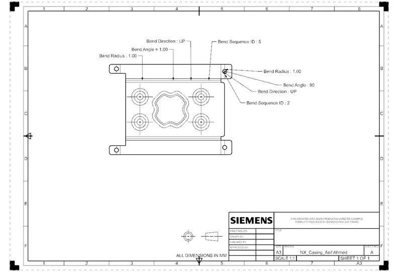
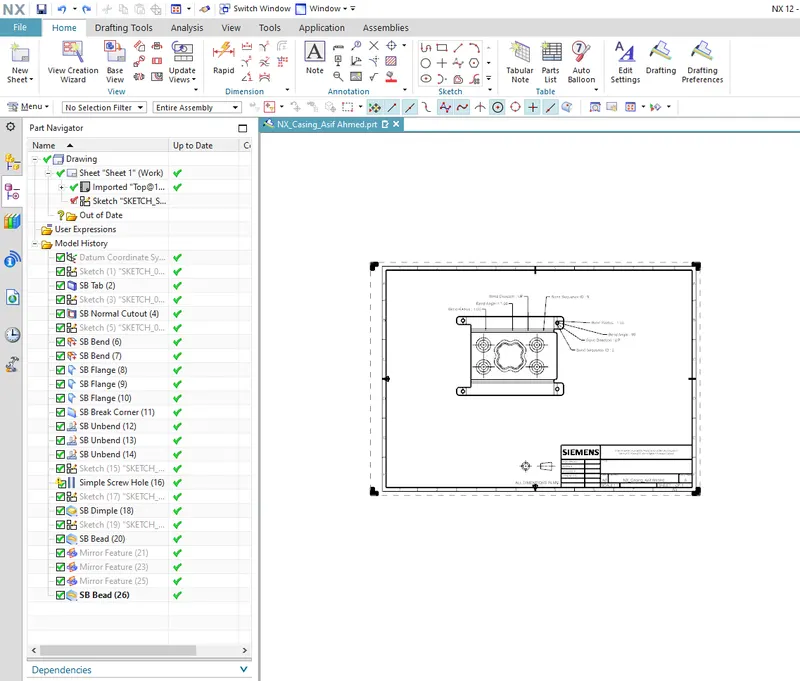
- Attach Detailed Drawing Sheet Image
- Conclusion
//
Note:-
Save the models with your name in prefix or suffix to the part name.
eg:
- NX_Casing_Your Name
//
Solution:
Introduction:
In Sheet metal Application we can create a uniform thickness Sheetmetal parts using basic features Such as Tabs, flange and jogs, we can also do bend corners, cut out, bead etc…features.
The Sheetmetal application provide an environment for the design metal parts used in machinery, Automotive and Aerospace Enclosures, Brackets and other parts are normally manufactured with break press.
The complex sheet metal part can be designed in the Solid model work Bench and then we convert in to Sheet metal part. We can also import, clean up and convert a non Sheet metal part into a valid Sheet metal part. Flat pattern Sheetmetal data can be used for the manufacturing process. The material parameters such as thickness, bend radii and bend relief can be easily set as default settings.
Design methodology:
Step 1: Create new sketch in XY plane of 60 mm & 50 mm rectangle
Step 2: Changing design parameters
Step 3: Adding thickness of 1 mm
Step 4: Sketching a rectangle of 5x40 mm long and cutting the same rectangle
Step 5: Applying Bending
Step 6: Applying flange of 5 mm
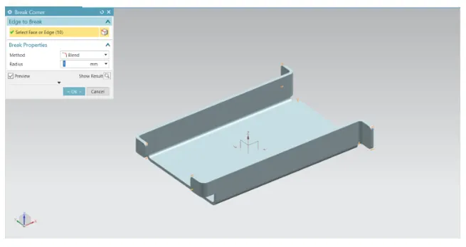
Step 7: Applting break corner of 1 mm
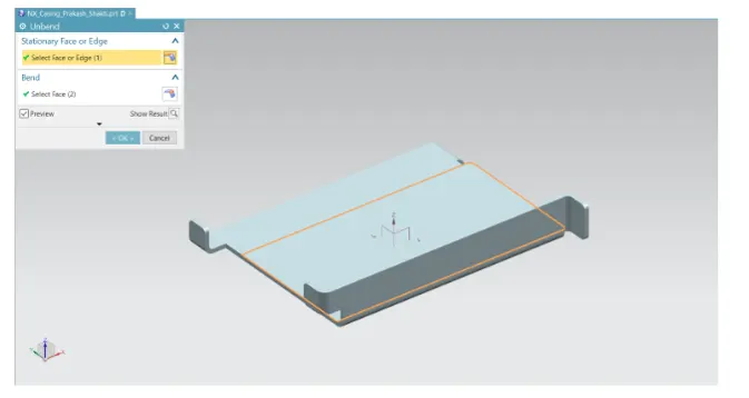
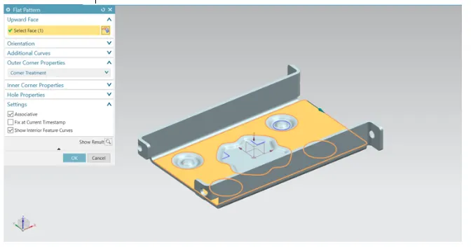
Step 8: Unbending the metal sheet
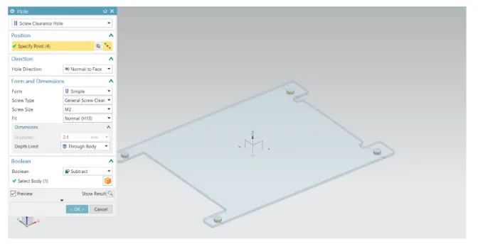
Step 9: Adding holes of M2 size
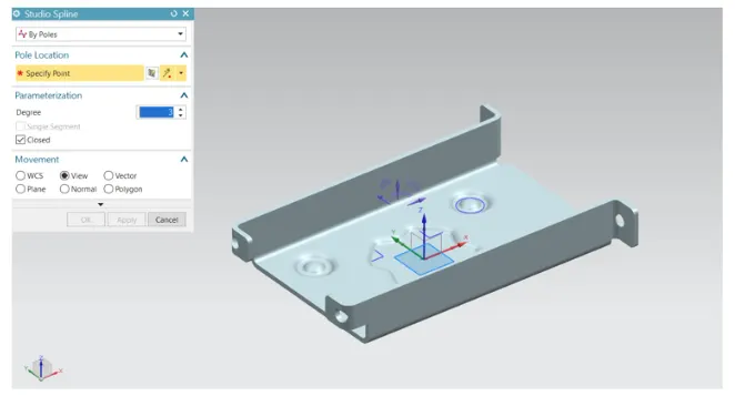
Step 10: Adding dimple in sketch
Step 11: Adding beads
Step 12: Re-bending the metal sheet
Step 13: Drafting.
CAD model with descripition:
Step 1:
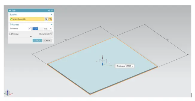
Step 2:
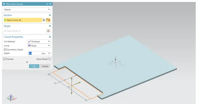
Step 3:
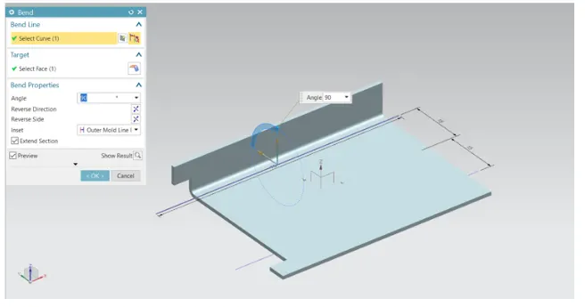
Step 4:
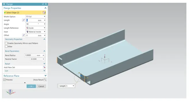
Step 5:
Step 6:
Step 7:
Step 8:
Step 9:
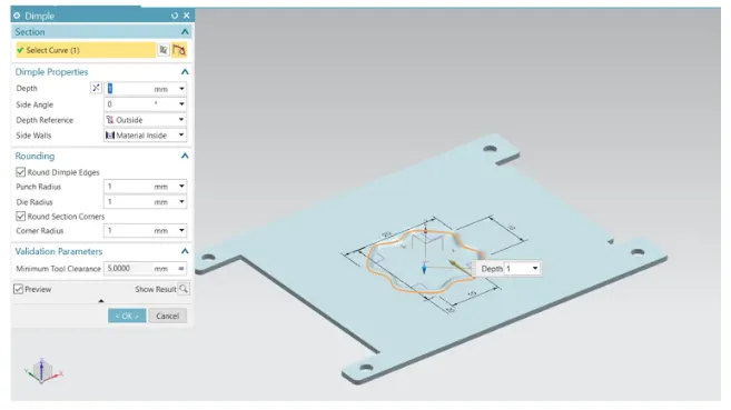
Step 10:
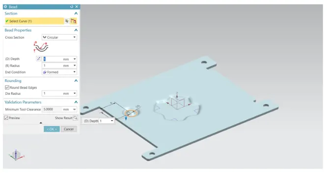
Step 11:
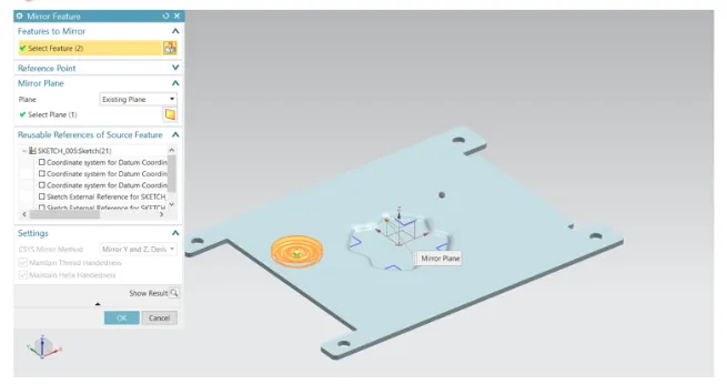
Step 12:
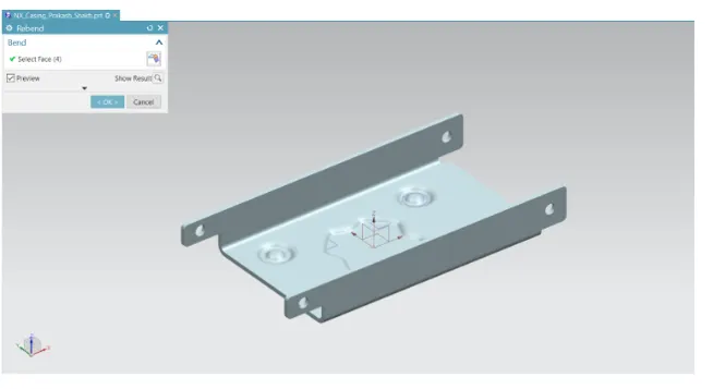
Step 13:
Drafting:
Conclusion
While designing a casing we have understand and learnt different tools such as Tab, Flange, Dimple, Bending, unbending and many more in sheet metal of NX.
Also, please find attached files for your reference.