Advanced Sheet Metal Design Using NX Cad Challenge_1_Casing Design
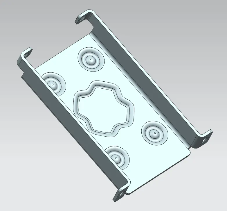
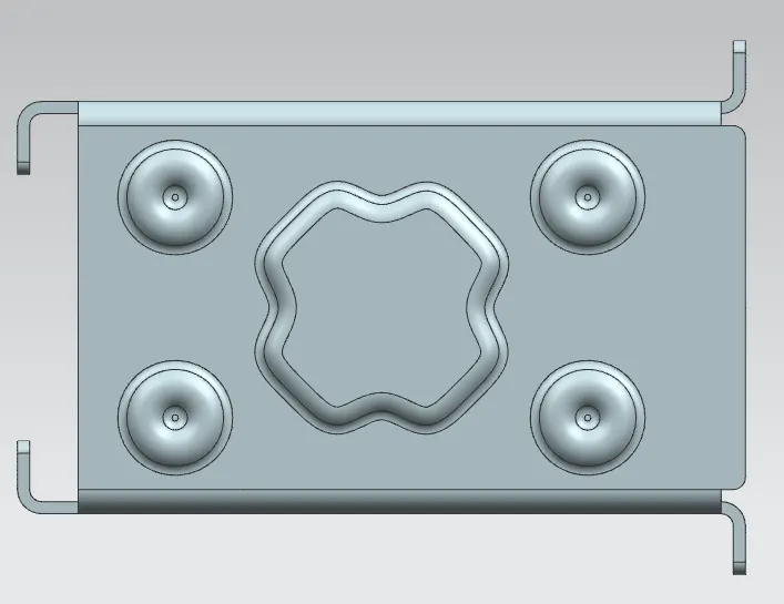
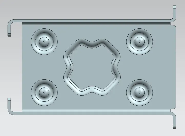
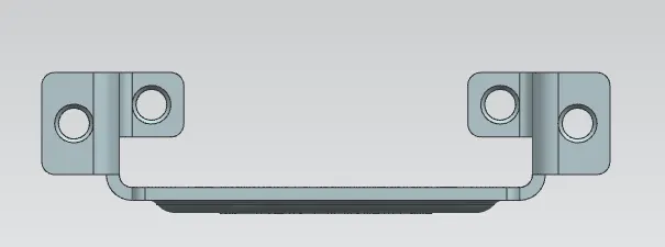
Creating the casing design using the sheet metal commands using NX cad
Objective: To create a sheet metal case.
Methodology:
- Start with creating the tab using the sketch inputs provided
- Use the normal cut-out to cut the shape
- Use the flange option to create the side flanges
- Eliminate the sharp edges using the break corner option.
- flatten the body using the unbend option and create the holes with the entry chamfer as shown in the below pictures.
- Create the dimple profile by following the input parameters mentioned in the tutorial
- Next, create the beads using the inputs
- Use the rebend to rebend and the model is completed.
- Now use the flat pattern option to obtain the flat model of the sheet.
Feature Information:
Tab command to create a base feature or a tab by extruding a sketch along a vector by a specified thickness value. You can also use this command to create a secondary tab if the work part includes existing sheet metal features. You can do this by adding material to existing faces and bend regions of an existing sheet metal part.
Use the Flange command to create a single flange instance or multiple instances by selecting single or multiple base edges.NX creates multiple flange instances in a single flange feature.
Contour Flange command to create a flange by extruding a sketch along a vector, or by sweeping a sketch along an edge or chain of edges. NX adds bends automatically using the default bend radius value. To use a different bend radius value, draw arcs in the section, or change the default bend radius value.
Use the Break Corner command to round or chamfer sharp corners of a tab or flange.
Use the Bend command to modify the model by bending material on one side of a sketch line, adding a bend between the two sides
Use the Unbend command to unbend a portion of the part to construct cutout features, hole features, or deform features across a bend. You can later reform the bend to represent the true formed state of the model.
Use the Rebend command to return an unbend feature to its previous bent state. Any features added after the unbend operation are properly repositioned during the rebend operation.
Use the Dimple command to lift an area of the model inside a sketch that simulates a stamping tool. You can create an indentation in a sheet metal part using a sketched section as the dimple outline.
Use the Normal Cutout command to cut material by projecting a sketch onto the model and then cutting perpendicular to the faces intersected by the projection