Advanced Sheet Metal Design Using NX Cad Challenge_1_Casing Design
Casing Design
OBJECTIVE:
To Write a detailed report on Sheet Metal Component with good explanation on Sheet Metal modelling tools applied throughout the modelling.
Introduction:
Sheet metal design software considers the fabrication methods needed for manufacturing. As you create flanges and add bends, the sheet metal design software will accurately represent the flat pattern required. The flat pattern can be used to document and manufacture associatively as the design changes. Here in this project we are dealing with the Sheet metal designing using the software Siemens Nx cad.
Design methodology / approach:
Casing is a part which can be an outer shell for various components or products which has various flanges, dimples, cut outs etc.
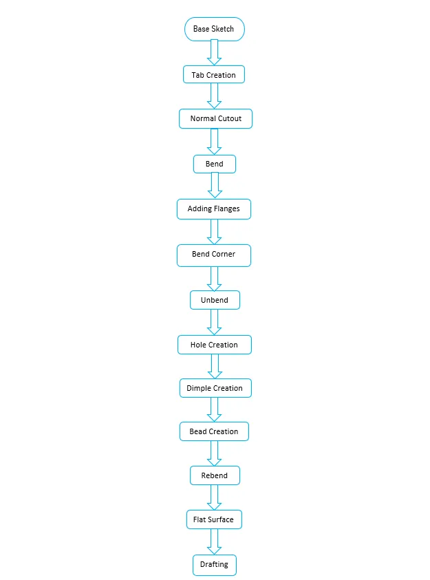
Description:
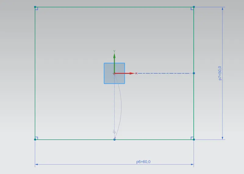
- SKETCH: This is used to create a basic sketch of the design on selecting the desired plane, then later it can be modeled for the requirement.
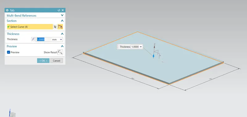
- TAB: Creates a base feature by extruding a sketch along a vector by a thickness value or adds material to a planar face. Additional planar sections can be added to generate bends as part of the base feature.
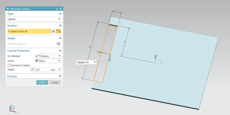
- NORMAL CUT OUT: Cuts material by projecting a sketch onto the model and then cutting perpendicular to the faces intersected by the projection.
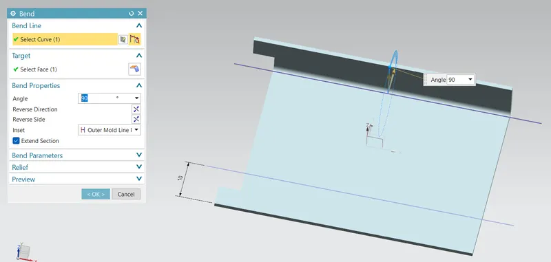
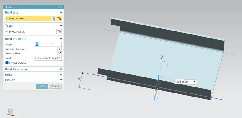
- BEND: Modifies the model by bending material on one side of one side of a sketch line, adding a bend between the two sides.
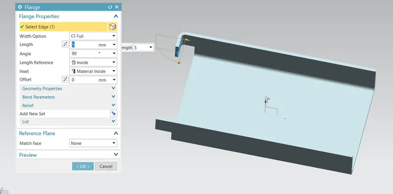
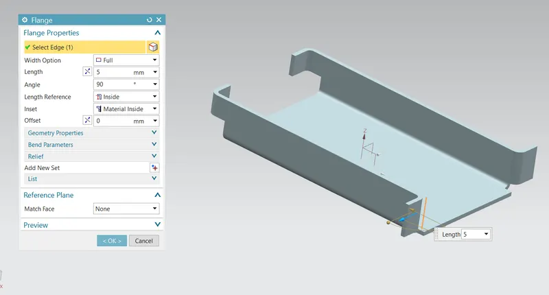
- FLANGE: Adds a flat flange at an angle to a planar face and adds a bend between the two.
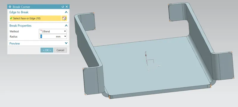
- BREAK CORNER: Rounds or Chamfer a sharp corner of a Tab or Flange.
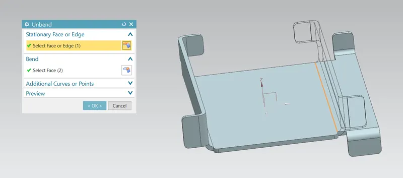
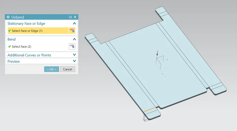
- UNBEND: Flattens a bend and the material adjacent to the bend.
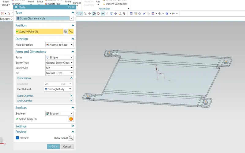
- HOLE: It is actually used for making the holes on the requirement for further assembly of the part by assigning different types of specifications of screws.
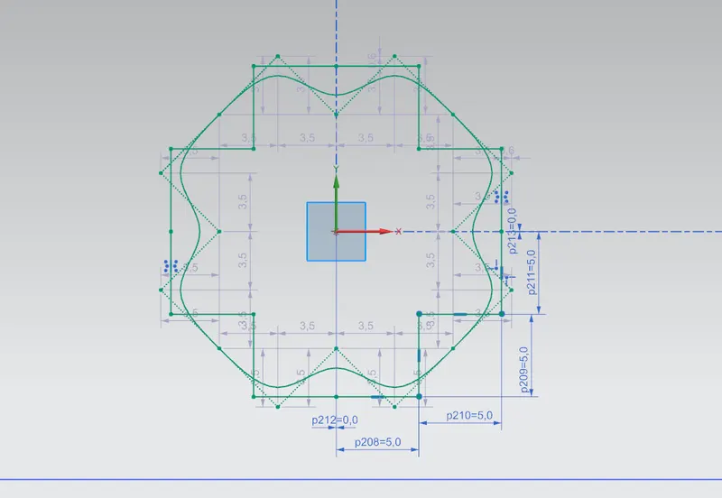
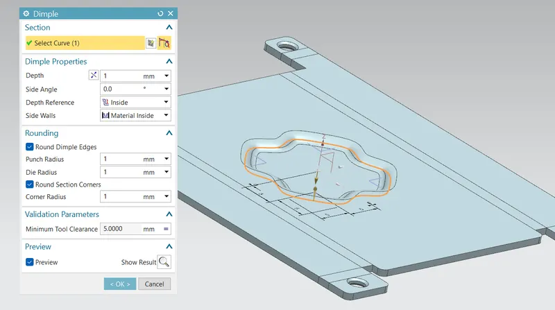
- DIMPLE: It is used to draw a dimple on selecting a curve for modeling the sheet.
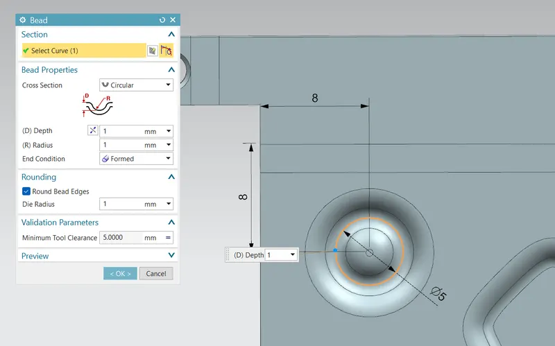
- BEADS: This feature is used to create a bead on the sheet which generally strengthens it. This tool is used to lift a material along the contour of a sketch that simulates a stamping tool.
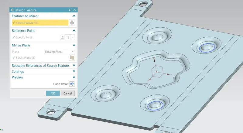
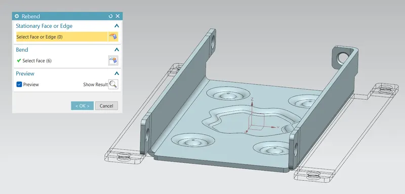
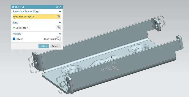
- REBEND: Restores an unbend feature to its previous bent state, along with any features added after the unbend feature.
Front view:
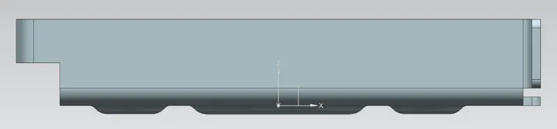
Side view:
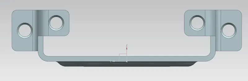
Top view:
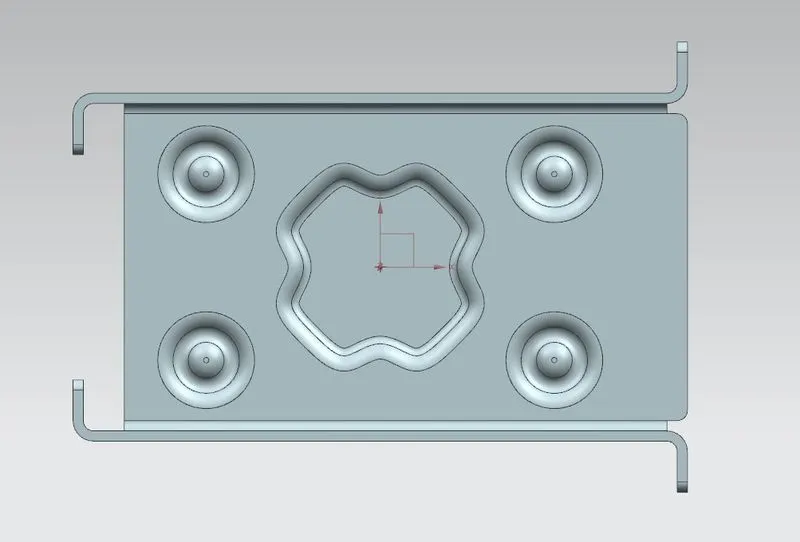
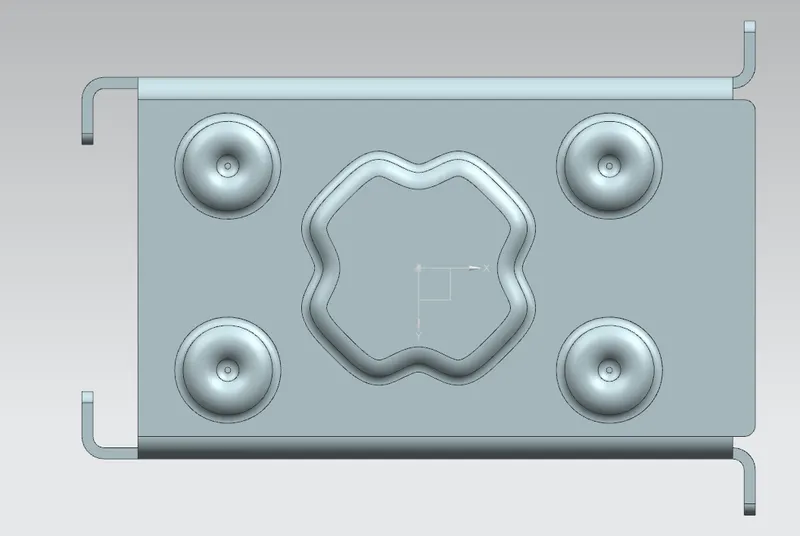
Bottom view:
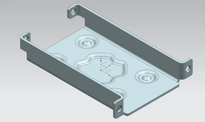
Isometric view:
- FLAT PATTERN: Creates a flat pattern from the formed sheet metal part. By using this flat pattern feature we can easily avoid error like interference or collision.
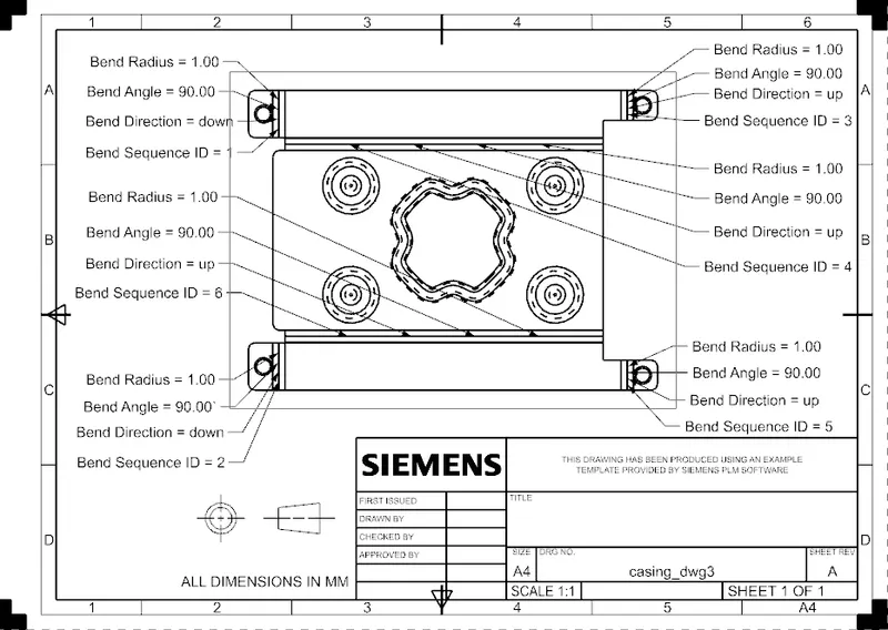
DRAFTING:
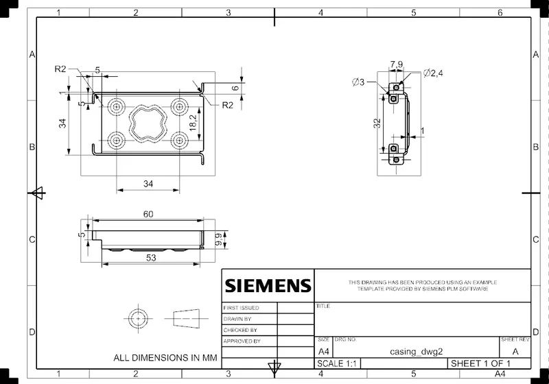
A new drafting file was created by selecting the A4 size sheet and added the base view by giving proper scale. The Flat Pattern View was created and imported in the blank sheet. Rotated the model as required.