Sheet Metal Casing Design
Objective:- To design a Sheet metal Casing Design using Siemens NX Sheet metal Application.
Introduction:-
NX Sheet Metal provides a set of tools within the NX design environment that allows for simple & fast design of sheet metal parts, dependent on their material & manufacturing process. NX sheet metal design software incorporates material & process information in sheet metal-specific modelling features: bends, flanges, tabs, cutouts, beads, dimples, corner, edge treatments, patterns and other formable features.
We can also quickly convert solid models to sheet metal components & create sheet metal parts that enclose with the other components.
NX Sheet Metal-specific features such as flanges, tabs, jogs, corner conditions, drawn cutouts and many more along with productivity enhancements such as – automatic bend reliefs.
Sheet metal is formed by an industrial process into thin, flat pieces. It is one of the fundamental forms used in metalworking and it can be cut and bent into a variety of shapes. "NX" it is formerly known as “Unigraphics” and is an advanced high-end CAD/CAM/CAE, which has been owned by Siemens PLM Software. Mostly it is used for Design, Engineering analysis, manufacturing.
Design Methodology:-
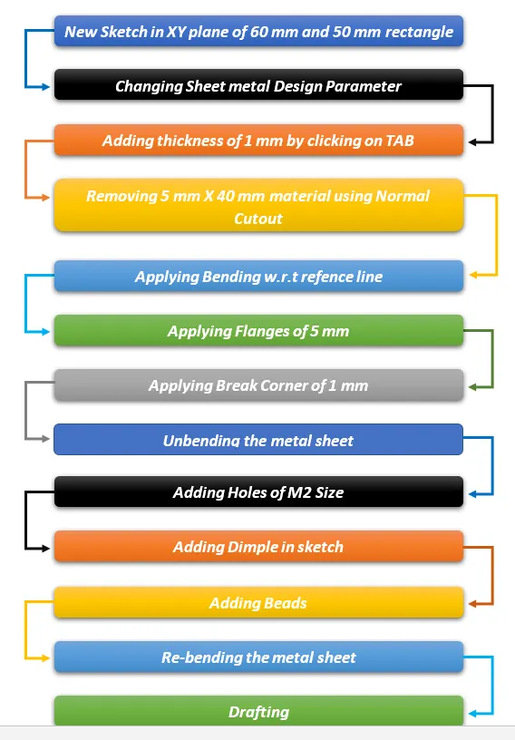
The design methodology can be explained by the following flow chart.
Description:-
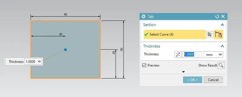
Step1: A sketch was created in the XY plane(P) a rectangle was of dimension 60X50 mm and then using the TAB button rectangular metal sheet of 1mm thickness was created.
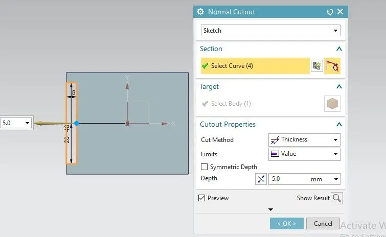
Step2: A rectangular sketch of dimension 5X40 mm was created at the left edge of rectangular sheet metal and that part was removed using the feature Normal Cutout.
Step3: In-plane P a horizontal line was drawn at a distance of 10mm from the upper left end corner of the metal sheet. By using the bend feature, the metal sheet was bent at an angle of 90 degrees. And the same process was repeated for a line drawn at a distance of 10mm from the lower left end of the sheet.
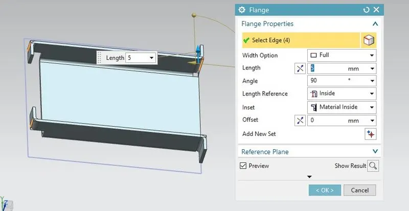
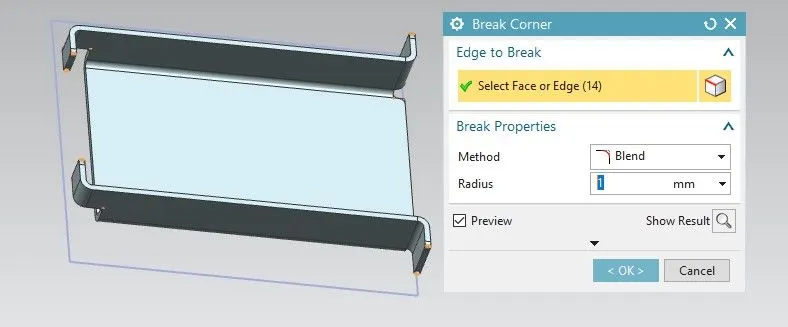
Step 4: Flanges of length 5mm were added at all joint portions of bent sheet metal by using the feature flange and make the fillet of radius the flange corner edges of radius 1mm using the feature Break corner.
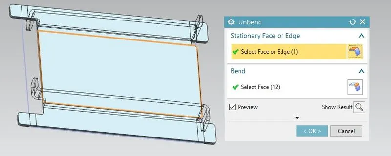
Step 5: The required portions were unbent for adding some punch features by using the feature called Unbend by selecting the larger horizontal sheet metal as the stationary face.
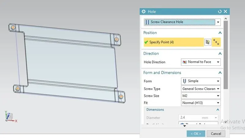
Step 6: For adding holes to the sheet metal, four circles were drawn which were symmetric about the origin and then holes were created by using the feature Hole of clearance hole with M2 Screw size and an H13 fit.
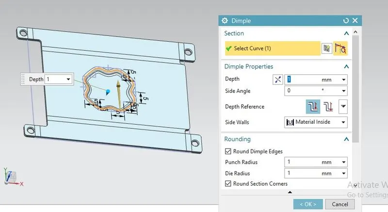
Step 7: In P plane i.e., XY plane requires sketch, where each half side is 5mm in length with centered at (0,0,0) and by using the studio spline, the required finished sketch was drawn at an angle of 45 Degrees. For the drawn sketch dimple was created by using the feature Dimple of depth 1mm.
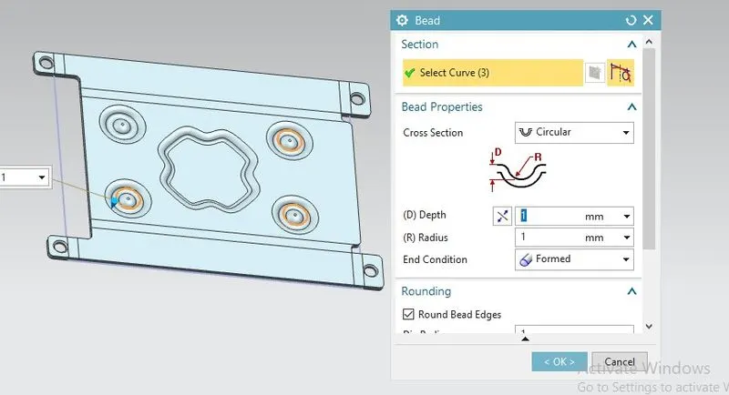
Step 8: In-Plane P a circle of diameter 5mm was drawn and by using the Bead feature required feature was created of depth 1mm.
Step 9: By using the Mirror feature create other beads on four corners along with the Dimple feature.
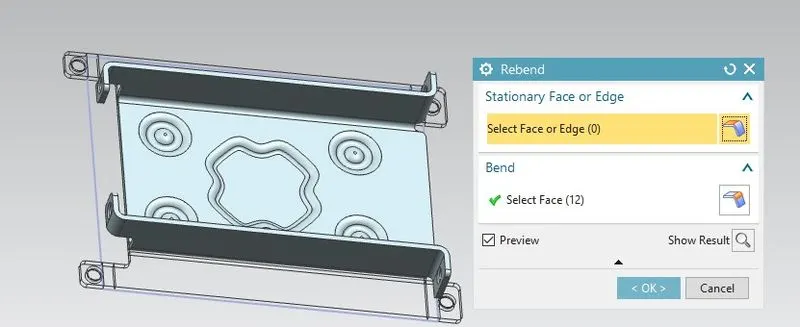
Step 10: The bent portions were rebent using the feature Rebend and finally the required casing was made.
Tab: - Use this command to create a base feature by extruding a sketch along a vector by thickness value, or by adding material to existing faces & bend regions of a sheet metal part.
Normal Cut out:- Use the Normal Cut out command to cut material by projecting a sketch onto the model and then cutting perpendicular to faces intersected by the projection. We can use planar sketches or 3D curves to specify the section for the normal cut out.
Bend:- We generally use this command to turn a sheet metal in various angle.
Flange:- Use this command to add a flat flange at an angle to a planar face and add a bend between the two. Bend consists of a two region
Break Corner:- Use the break corner command to round or chamfer sharp corners of a tab or flange.
Unbend:- Use the Unbendcommands to unbend and rebend non-uniform thickness bends.
A Screw Hole :- This command use for create a screw size hole in sheet metal.
A Studio Spline:- Use the Studio Splinecommand to dynamically create splines using either points or poles.
Move Curve:- Use the Move Curvecommand to move or rotate a set of sketch curves.
Bead:- Use the bead command to lift material along the contour of a sketch that simulates a stamping tool. Beads can also be created to stiffen sheet metal part.
Rebend:- Use the Rebendcommands to unbend and rebend non-uniform thickness bends.
Flat pattern view :- A flat patternis a 3D sheet metal model in a flattened state. Create Flat Patterncalculates the material and layout required to flatten a 3D sheet metal model. The part browser displays a Flat Pattern node, and the flattened state of the model displays when this node is active.
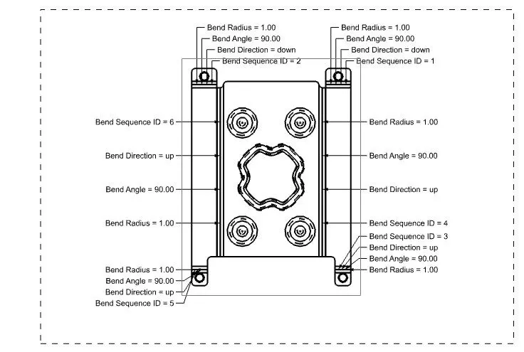
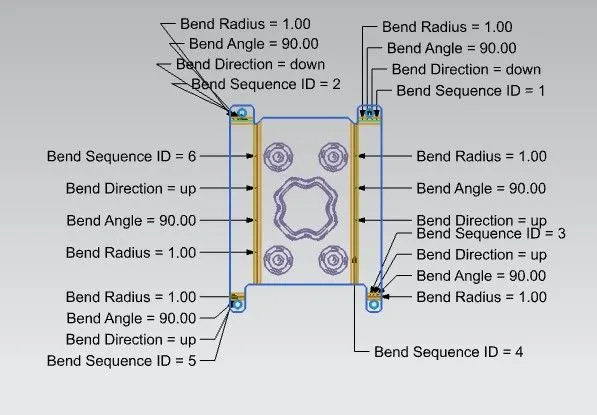
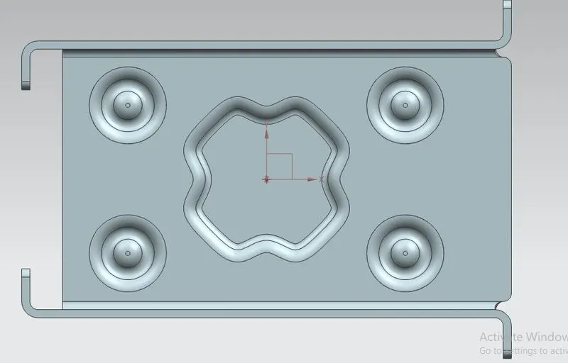
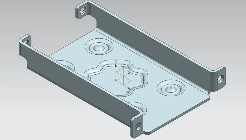
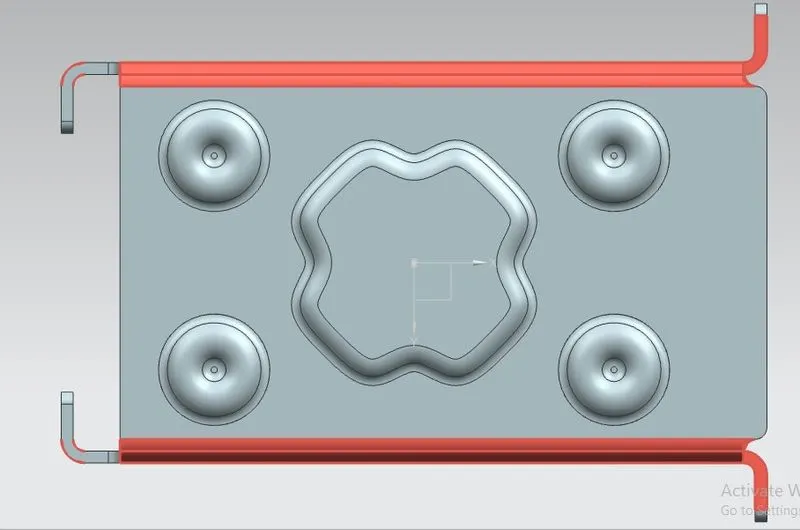
Views of the model are as follows:-
Top view
Isometric view
Bottom view
Front view
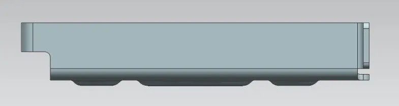
Right hand sided view
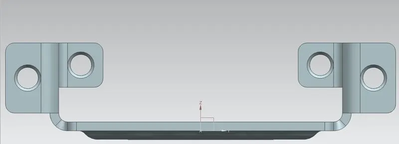
Flat solid view
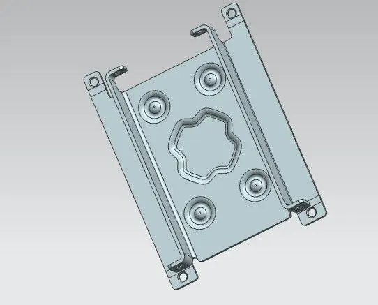
Studio view
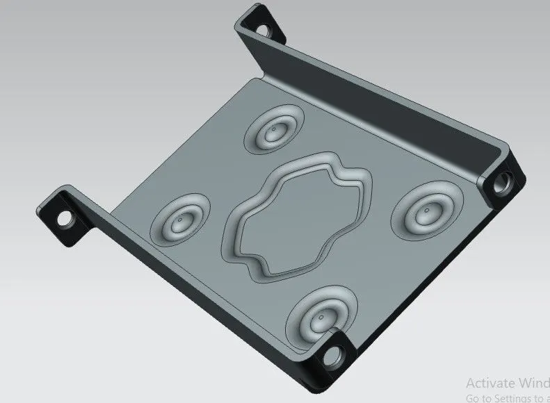
Shaded view
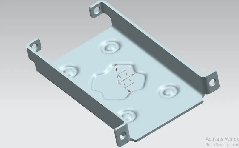
Conclusion:- By using various commands in sheet metal design, "CASING DESIGN" was created by various features.