Advanced Sheet Metal Design Using NX Cad Challenge_1_Casing Design
Casing Design
Aim: - To design an advanced casing using the sheet metal application in NX.
Objective:-
Sheet Metal Fabrication is the process of forming parts from a metal sheet by punching, cutting, stamping, and bending. 3D CAD files are converted into machine code, which controls a machine to precisely cut and form the sheets into the final part. Sheet metal parts are known for their durability, which makes them great for end use applications (e.g. chassis). Parts used for low volume prototypes, and high volume production runs are most cost-effective due to large initial setup and material costs.
Introduction: -
Sheet metal design is a vast domain in the design industry. It is used in many sectors including the automotive sector. In this sheet metal casing design, we will look at the design approach using the Siemens NX (CAD) software through various diagrams, explanations and images.
Sheet metal is metal formed by an industrial process into thin, flat pieces. Actually, it is one of the fundamental forms used in metalworking, and it can be cut, bent into a variety of shapes.
Many other different metals can be made into sheet metal, such as Aluminums, brass, copper, steel, tin, nickel, and titanium. For decorative uses, some important sheet metals include silver, gold, Platinum.
Sheet metal is generally used in automobiles, airplane fuselages, wings, and also in utensils. To manufacture all these in different designs and preparing drafting in the desired way by a manual drawing cannot be performed. If we use the design tools to do this can be a better choice and helps in modeling the object can be done easily.
Features
Tab: - Tab is only used in designing of sheet metal. Tab is base where the flange can be formed.
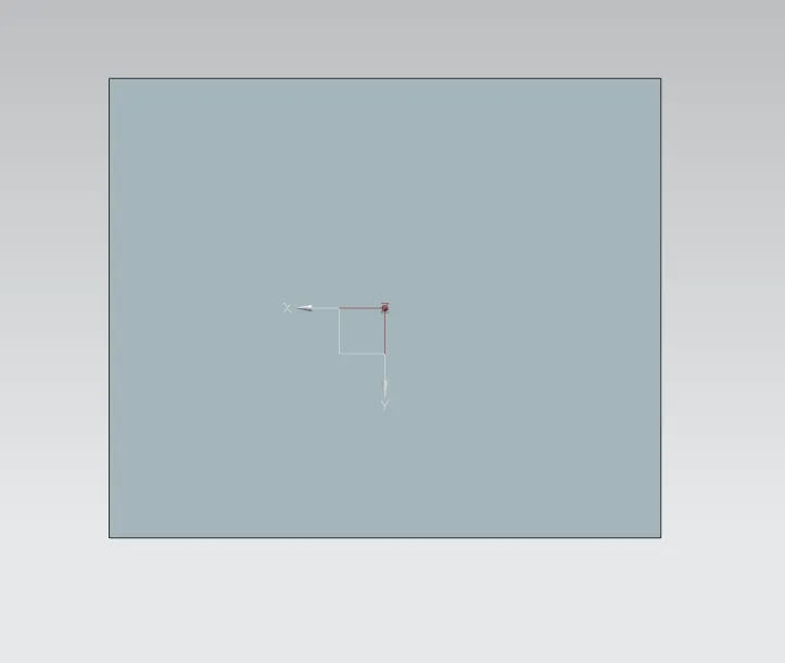
Bend: - This feature is used to bend the sheet metal along the sketched curve upon our requirement.
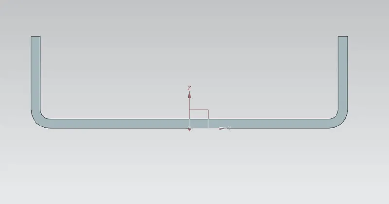
Flange:- Flange is used to add flange on selecting the edges of our sheet metal, it is working as a Bend features along with that extra material can be added by adjusting the length of the flange.
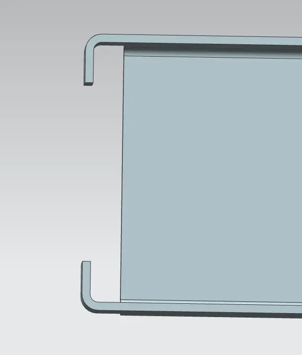
Break Corners: - Break Corners are used to make the edges round for easy handling when using.
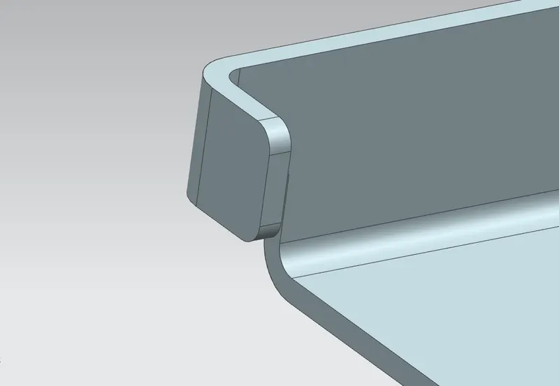
Unbend: - Unbend is features used to analyze the model whether a part was perfectly assigned the features, which ensures for a modeler to do further operations on it.
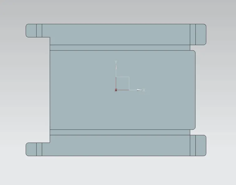
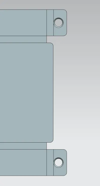
Holes: - It is actually used for making the holes on the requirements for future assembly of the part by assigning different types of specifications of screws.
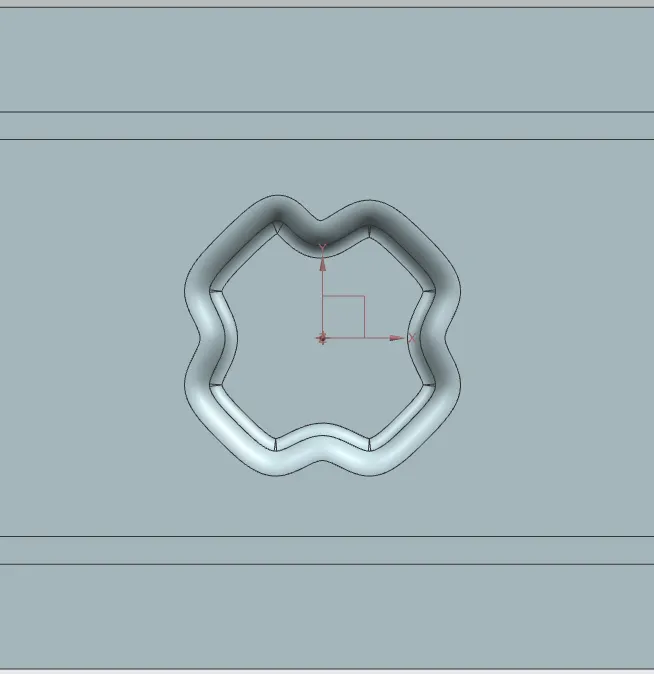
Dimple: - It is used to make the draw type shape.
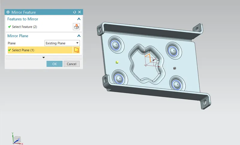
Mirror: - It is used to add the material or feature replicates by acting as a mirror to it, this generally reduces the modeling time.
Re-bend:- This is used to re-bend the object after all conformation and ready for production.
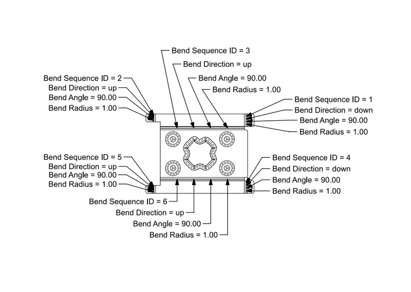
Drafting: - It is used to provide the dimensions and views of the 3D designed part to the manufacturing team.
Procedure: -
Step1:- Initial Design parameters such as Material Thickness, Relief Depth, Bend Radius and Relief width for the sheet metal are to be changed to 1mm.
Step2:- The base feature of the casing is designed by drawing a 2D sketch in the plane.
Step3:- The features Tab is created with the help of 2D sketch drawn.
Step4: -Then another sketch of rectangle is created on the plane with 5mm wide and 40mm long with the edge coincide with left end of the tab created previously and then features normal cutout is performed with the sketch created.
Step5: - A sketch is created again on the plane and it consists of 2 horizontal lines which is drawn parallel and symmetric about the axis.
Step6:- The bending is performed by creating the sketch and the angle of bending is 90 degree for both the lines.
Step7:- The feature flange is performed. It is applied to 4 edges inside and outside based upon the procedure.
Step8: - Then the feature break corner is applied to sharp edges of the casing with the radius of 1mm.
Step9:- The un-bend of the sheet metal is done by selecting the large face of the tab created for the reference and then the corresponding bend face.
Step10: - The hole is created on the same plane with the radius of 5mm on the surface of four unbends.
Step11: - Created the sketch on the tab face and Dimple operation is performed.
Step12: - To perform bead, a sketch consists of circles is created on the tab surface.
Step13: - To perform the mirror features and mirror the beads to the other side.
Step13: - The flat pattern is done by selecting the flat face of the sheet metal for the reference.
Step14: - Then creating the drafting drawing.
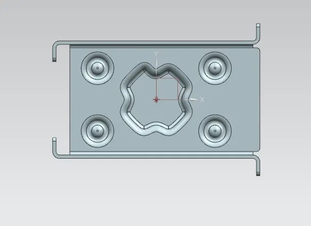
Top View
Front View
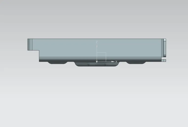
Side View
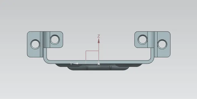
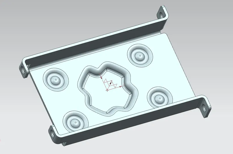
Isometric View
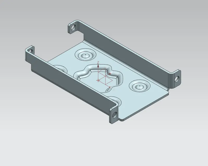
Drafting
Conclusion: - I have learned about the sheet metal and created the casing using the sheet metal.