Advanced Sheet Metal Design Using NX Cad Challenge_1_Casing Design
Title : Report on Sheet Metal Component.
Objective : A detailed report on Sheet Metal Component and about Sheet Metal modelling tools applied throughout the modelling.
Introduction : Start the NX and Open a new file for creating a sheet metal ,giving the dimension as required for casing .Giving the flanges,punch.
Design Methodology
| Open the NX |
| Starting as new file . |
| Desiging the sheet metal as required . |
| saving the model and exit . |
Descreption :
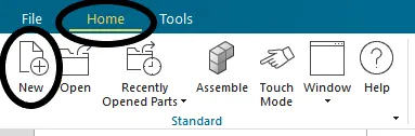
* Open Nx , click to home from tab and select the new ,select the type as rerquired which is shown below .
* Home tab is a starting page to design a sheet metal,model,assembly,shape studio.
* New tab is the process of opening the model as required i,e. sheet metal,model,assembly,shape studio.as shown below;
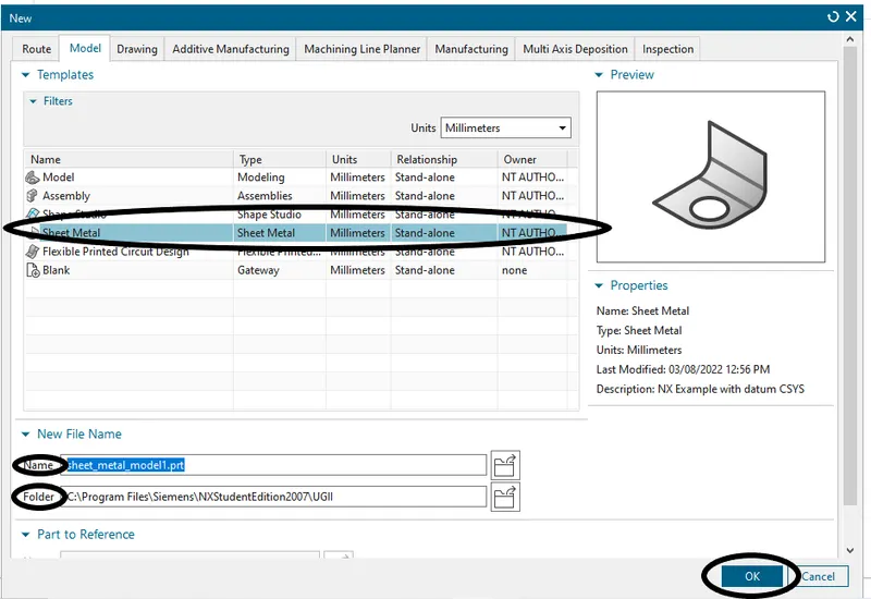
* Here ,we select the type as sheet metal for design .
* Sketching the sheet Metal.
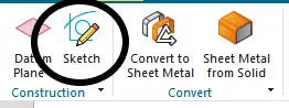
* Sketch Tab is the process of designing the model with proper dimensions .
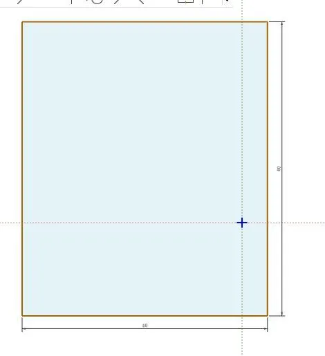
* After Selecting the new file from home tab ,select sketch to design and select the XY plane for a rectangle with appropriate dimension .
* Draw a rectangle from origin of X-length of 60mm and Y-length of 50 mm as shown below.
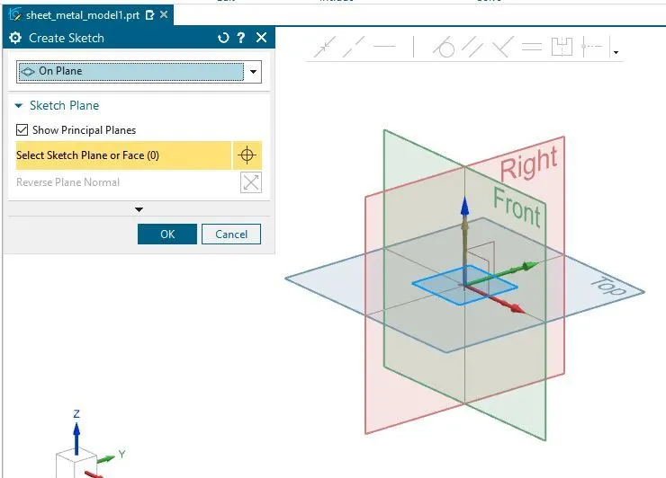
* The sheet image of rectangle are given below ;
* Performing a tab
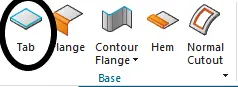
* Tab is a process that creates a base feature by extruding a sketch along a vector by a thickness value .It creates the a feature as per the sketch .
*After designing the Rectangle go to tab and select a edge hence it selects the complete rectangle .
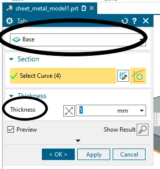
* Keeping in base ,as there is secondary plane .Applying the thickness and click ok as shown below in encircled region.
* Sheet image :
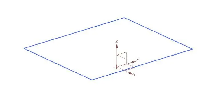
* Before Performing Tab .
* After Performing Tab .
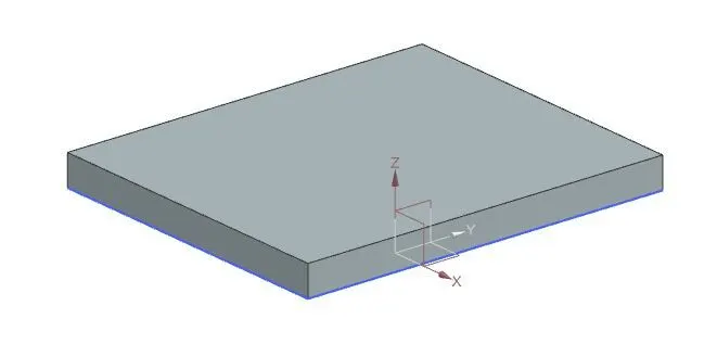
* Here, a solid body is created .
* Performing of Cutout :
* Cutout : It Creates material by projecting a sketch onto the model and then cutting perpendicular to the faces intersected by the projection .
* The cutout peforms as it cut the material upto the selected point or throughout the point .
* After Performing of Tab ,Go to sketch keepin in on plane ,click ok and perfrom a rectangle .
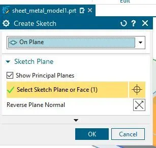
* Sheet image :
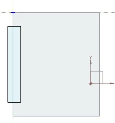
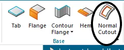
* Now from groups select Normal cutout and give deapth as 5mm and click ok as shown below .
* Before Performing Cutout .
* After Performing Cutout .
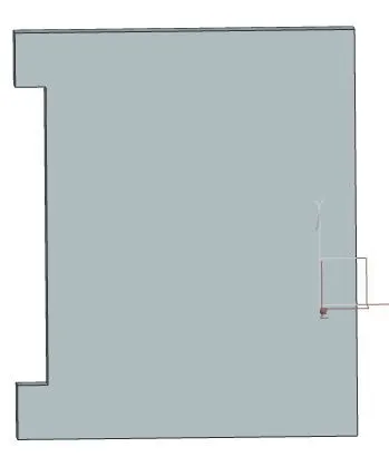
* Performing of Bend :
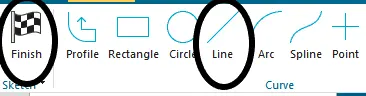
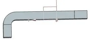
Bend : Bends the material one a side of sketch line and adds bends between the two sides .
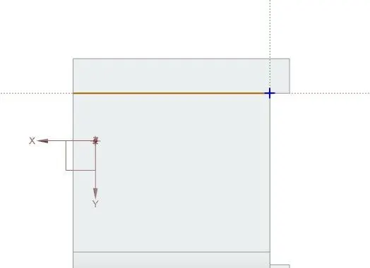
* Select the sketch from tool tab and sketch a line keeping in on plane as required .
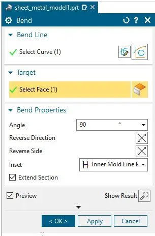
* Now click to bend and select line ,draw a line vertical to the model .moreover select the line .
* Select the appropriate direction for bend and click ok.
* Sheet image :
* Performing the bend in other side :
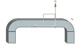
* Select the sketch from tool tab and sketch a line keeping in on plane as required .
* Now click to bend and select line ,draw a line vertical to the model .moreover select the line .
* Select the appropriate direction for bend and click ok.
* Sheet image :
* Performing of flanges :
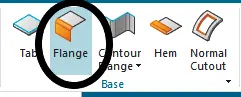
Flanges : Is the process that adds a flat flange at an angle to a planar face and adds a bend between the two .
* Here, the flange are performed at the edges of surface .
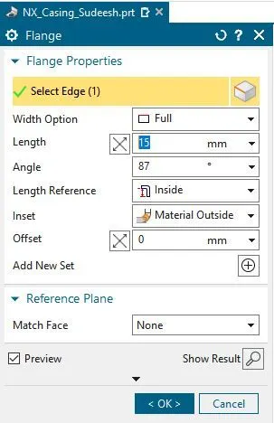
* From the tool tab,click to flange and select the edge of a surface, with length 15mm click apply .
* Give the dimesions for flange as shown encircled below .
* Model before performing Flanges :
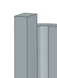
* Model After performing Flanges :
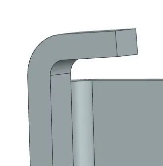
* Model before performing Flanges :
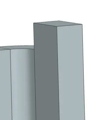
* Model After performing Flanges :
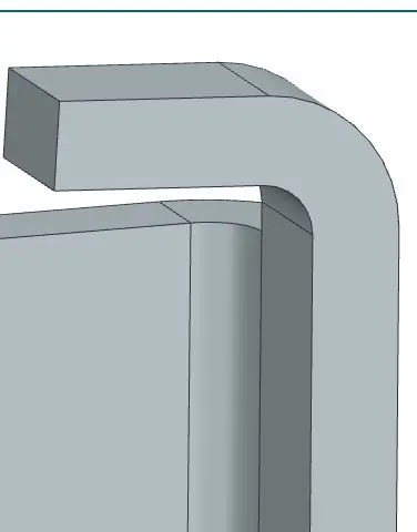
* Model before performing Flanges :
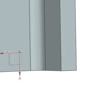
* Model After performing Flanges :
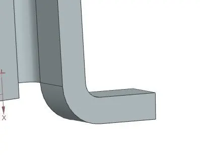
* Model before performing Flanges :
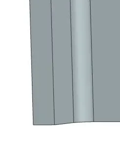
* Model After performing Flanges :
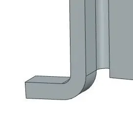
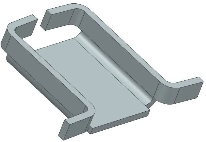
* Model after completing the flanges .
* Breaking Corner :
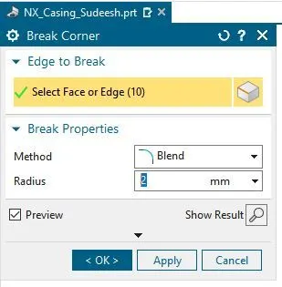
*It basically rounds or chamfers the sharp edges of tab or flanges with given radius .
* Select the break cornor from tool bar and give the required radius for sharp edges ,click ok.
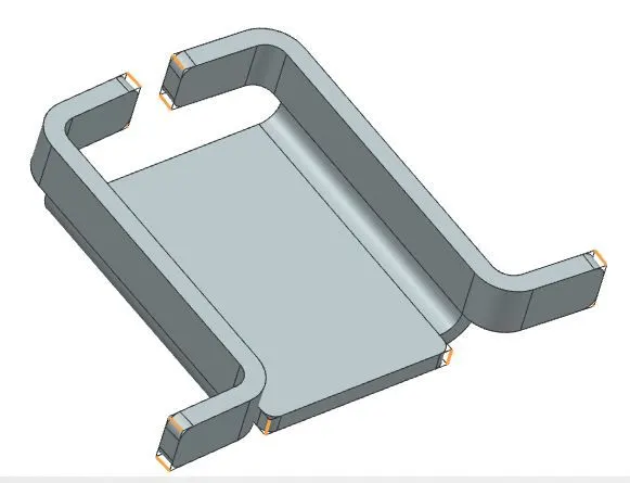
* Model Before performing Breaking Corner :
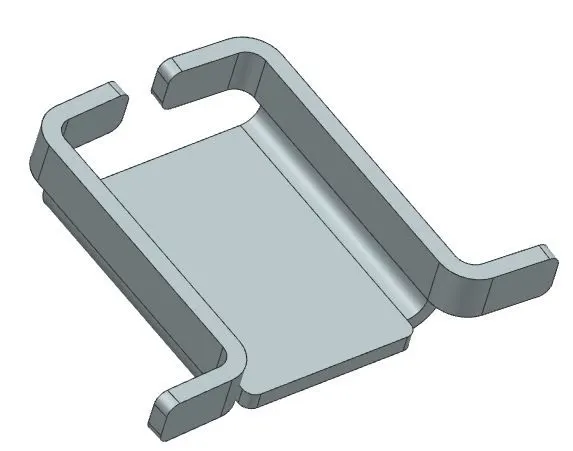
* Model After performing Breaking Corner :
* Performance of Unbend :
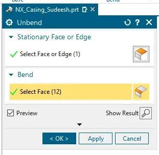
Unbend : Flatters a bend and the material adjecent to the bend
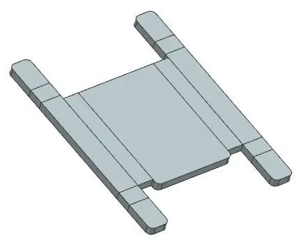
* It Flatters the surfaces completey ,with repesct to selected surafces.
* From tool bar select the unbend ,moreover Select the Stationary surface and select another surface which need to flatter ,click ok the surafce gets flatter as shown below.
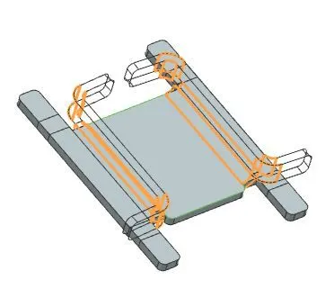
* Model before unbending :
* Model After unbending :
* Performing o Hole:
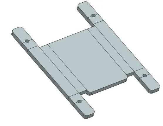
Hole : It Create cutout throughout or at required deapth by selecting a point given by sketch ,with given radius .
* From tool bar select sketch and draw a line ,moreover select the hole tab ,it assits to select a point where the hole has to performed .
*Give the dia or raidus accordingly and click ok as shown below .
* Before performing hole tool :
* After performing hole tool :
* Adding Dimple :
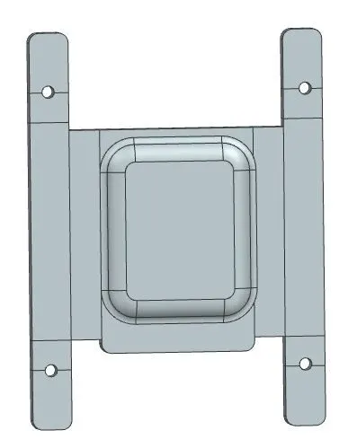
Dimple : It lifts the area of the model inside a sketch that stimulates a stamping tool.
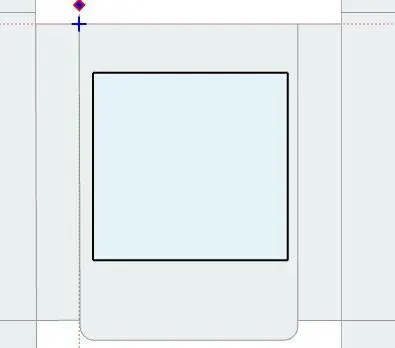
*Select the surface area of model and sketch with given dimension .
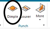
*Now , select Dimple from tool bar and also select the sketch to be dimpled .
* Give the depth as 2mm and click ok as shown below;
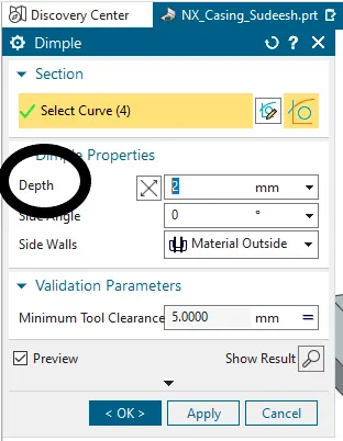
* Sheet image :
* After performing Dimple :
* Rebending :
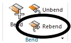
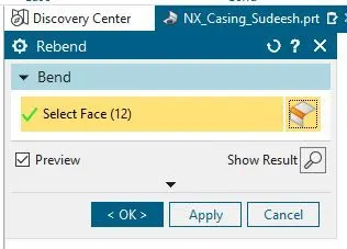
Rebending : This process rebends the unbend feature to its previous bent state,along with any features added after the unbend feature .
* Click rebend form tool bar and select the model to be rebended as shown below .
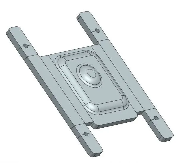
* Model Before Rebend :
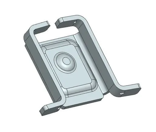
* Model after Rebend :
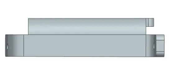
* Front view :
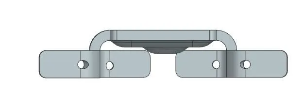
* side view :
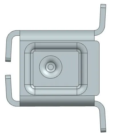
*Top view :
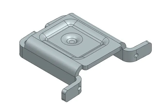
* Isometric view:
* Concluison : Hence,we are able to design the casing with dimension as required and this sheet metal model .Can furthur it can be subjected to analysis .