Advanced Sheet Metal Design Using NX Cad Challenge_1_Casing Design
CASING DESIGN
Objective: To draw the given sheet metal component '"Casing Design" as per the given dimensions and making the draft sheet by using the Siemens NX CAD software.
Introduction:
- The given casing design is an example to be designed in the sheet metal operations in NX CAD.
- This casing design can be used in the automobile field and for other fields this casing can be of other form.
Design Methodology:
1. Sketching the given shape
2. Constrution of features
3. Adding the features
4. Giving unbend and punch features
5. Creating flat pattern/Drafting
Features/Tools used:
1. Sketch: It creates a sketch in the current application and we can use the direct sketch tools to add curves, dimensions, constraints, etc.
2. Rectangle: Using this tool, we can create a rectangle using any of the three different methods i.e., by 2 points, by 3 points or from center.
3. Finish Sketch: It will deactivates the active sketch or exit the current sketch.
4. Sheet metal preferences: This feature is used to provide the fixed preference values throughout the design and some other properties.
5. Tab: It creates a base feature by extruding a sketch along a vector by a thickness value, or adds material to a planar face. Additional planar selections can be added to generate bends as part of the base feature.
6. Normal cutout: This tool cuts the material by projecting a sketch onto the model and then cutting perpendicular to the faces intersected by the projection.
7. Bend: This tool modifies the model by bending material on one side of a sketch line, adding a bend between the two sides.
8. Flange: It adds a flat flange at an angle to a planar face and adds a bend between the two faces.
9. Break corner: This tool is used to make rounds or chamfer a sharp corner of a tab or a flange.
10. Unbend: This tool flattens a bend and the material adjacent to the bend.
11. Hole: It adds a hole to one or more solid bodies in a part or assembly with options for counterbored, countersunk and threaded.
12. Studio Spline: This tool dynamically creates and edits splines by dragging defining points or poles, and assigning slope or curvature constraints at defining points.
13. Move curve: This is used to move a set of curves and adjusts adjacent curves to accommodate.
14. Dimple: This tool lifts an area of the model inside a sketch that simulates a stamping tool.
15. Bead: This tool lifts the material along the contour of a sketch that simulates a stamping tool.
16. Rebend: It restores an unbend feature to its previous bend state, along with any features added after the unbend feature.
17. Flat Pattern: It creates a flat pattern feature from the formed sheet metal part.
18. Base View: This feature creates a model based view on the drawing sheet.
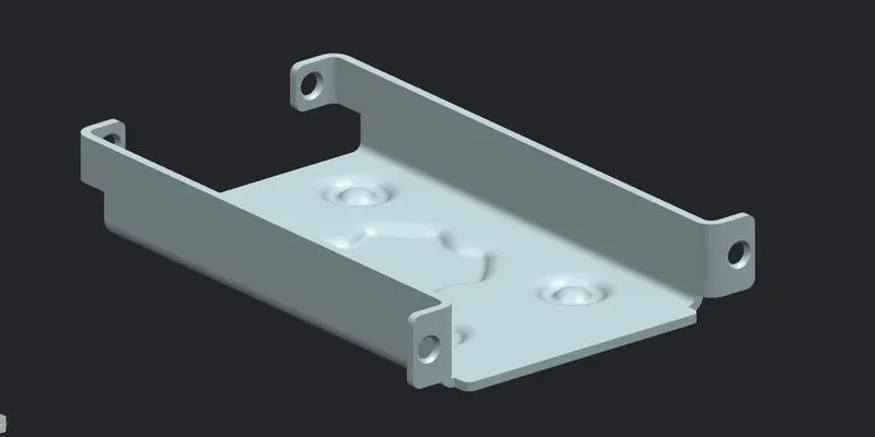
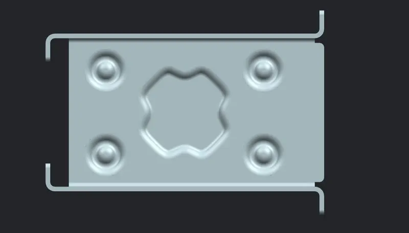
Trimetric view Top view
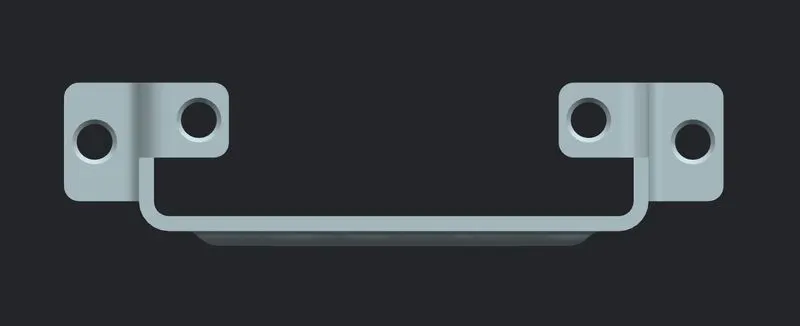
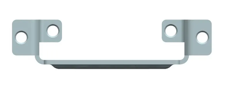
Left view Right view
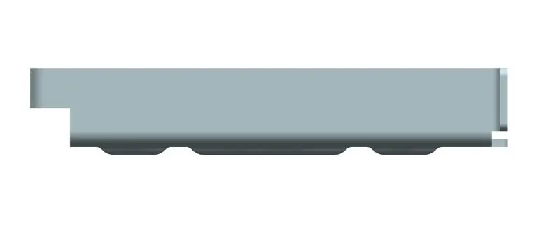
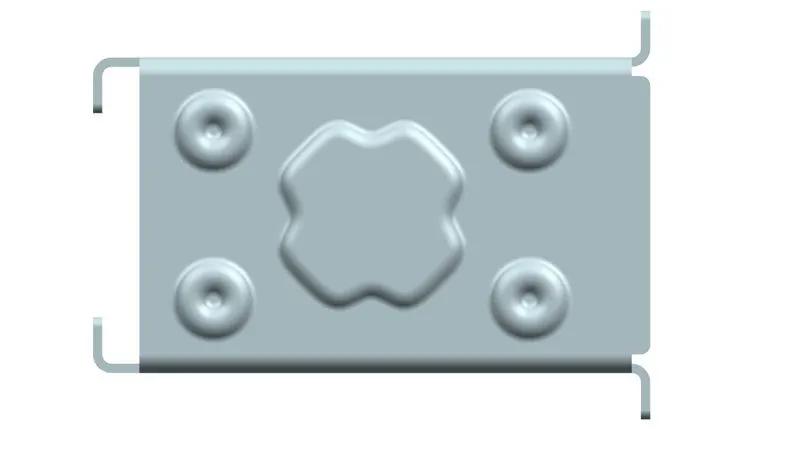
Front view Bottom view
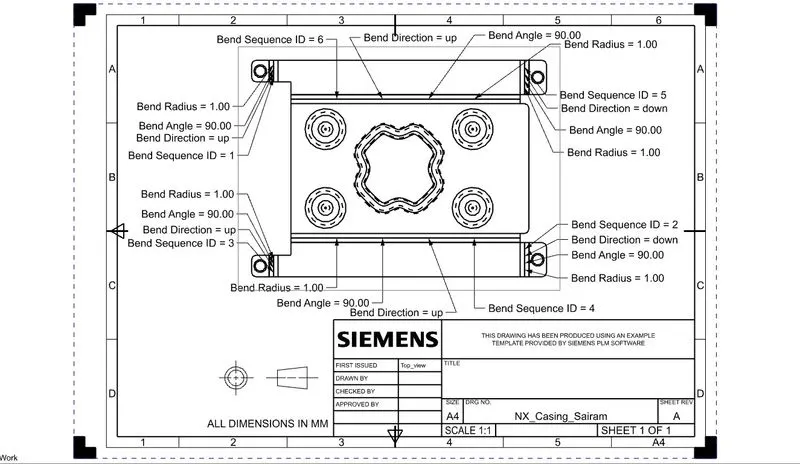
Draft_Sheet
Conclusion: So the given sheet metal component has been made with the given dimensions and also draft sheet is derived by using the Siemens NX CAD software.