Advanced Sheet Metal Design Using NX Cad Challenge_1_Casing Design
CASING DESIGN
AIM:
To create a sheet metal component of Casing with explanation of which tools used to create the component and to write detaile report.
INTRODUCTION:
SHEET METAL DESIGN:
Sheet Metal Fabrication is the process of forming parts from a metal sheet by punching, cutting, stamping, and bending. 3D CAD files are converted into machine code, which controls a machine to precisely cut and form the sheets into the final part.
DESIGN METHODOLOGY
MODEL DESIGN:
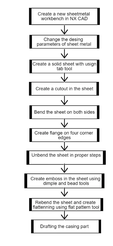
First create a new sheetmetal model in NX Cad tool software and check the sheetmetal design parameters,make global parameters such as Material thickness, Bend radius, Relief width and depth as 1mm.
TAB:
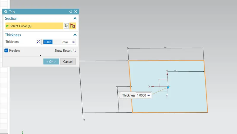
Create a base feature by extruding a sketch along a vector by a thickness value or adds a material to a plane surface
Create a rectangular sketch wiht dimension of 60mm x 50mm and make it solid sheet by using tab tool.
NORMAL CUTOUT:
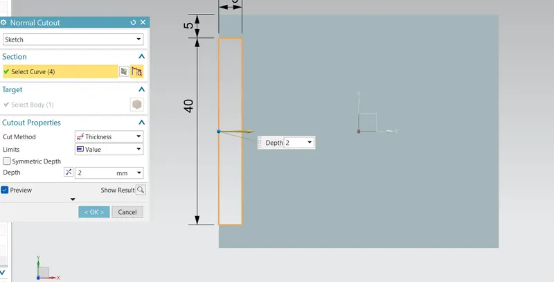
Cuts the model perpendicular to the sketch.
Cut the portion in the left side of sheet model using Normal cutout tool with creation of rectangle sketch in 40mmx5mm.
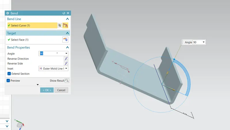
BEND:
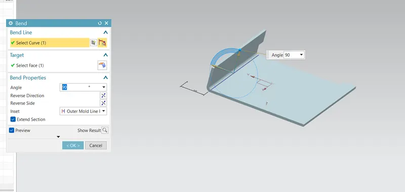
Modifies the model by bending material on one side of a sketch line adding a bend between the two sides.
Bend the sheet metal in both sides using bend tool with help of sketch a line on sheet from the edge as 10mm.
FLANGE:
Adds a flange to an angle to a planar face and adds a bend between the two..
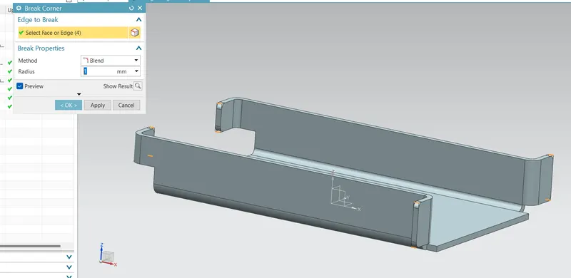
BREAKEUP CORNER:
Rounds a sharp corners.
Create flange on four side edges in 5mm length and angle 90 degree and breakeup the flange corners smooth in radius of 1mm.

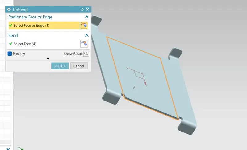
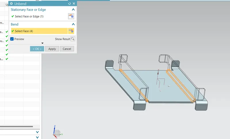
Unbend all the bended portions and flanges
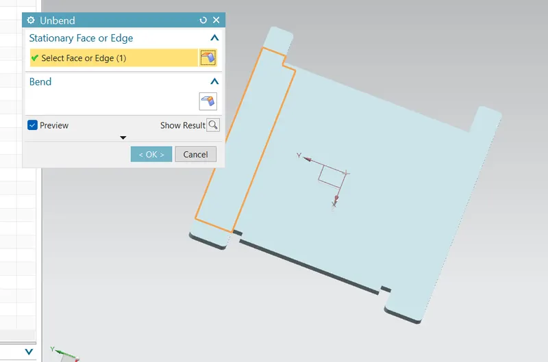
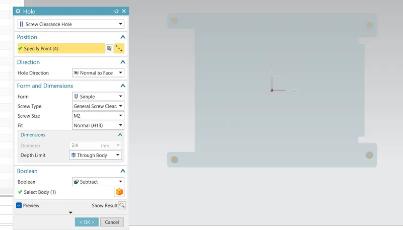
Create hole on four corners in the sheet model.
DIMPLE:
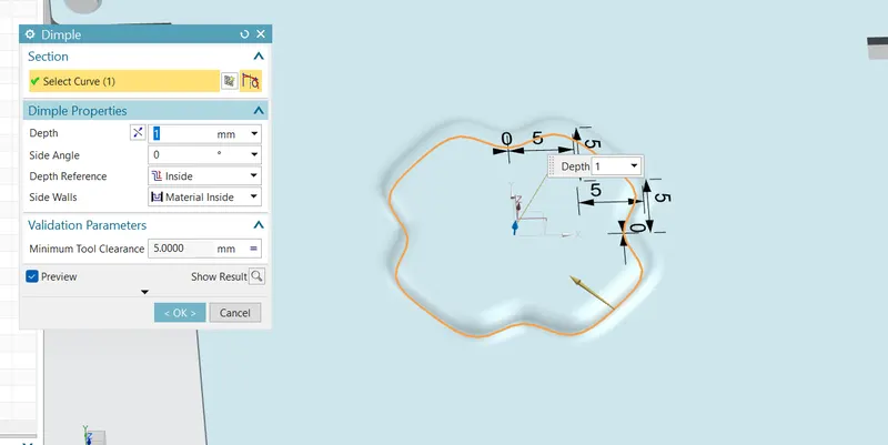
Lifts an area of the model inside a sketch that simulates stamping a tool.
Create embossing in the center of the plate with sketch wrt to dimensions and using dimple tool.
BEAD:
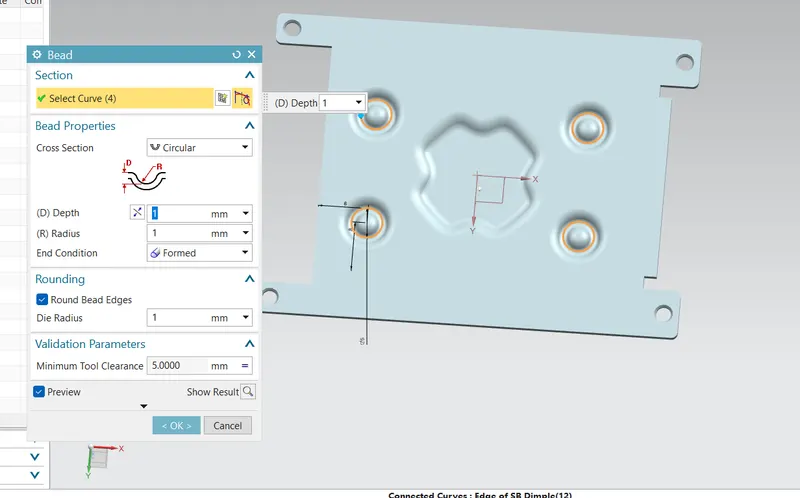
Lifts a material along a counter of sketch that simulates stamping a tool.
Create bead on sides in sheet by using bead tool wrt depth,radius and roud bead eges as 1mm.
FLAT PATTERN:
Creats a flat pattern feature from the fromed sheet metal part.
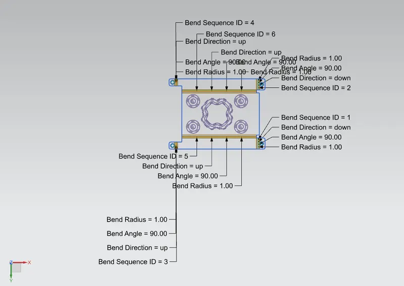
Rebend the sheet in order of bended steps.
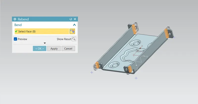
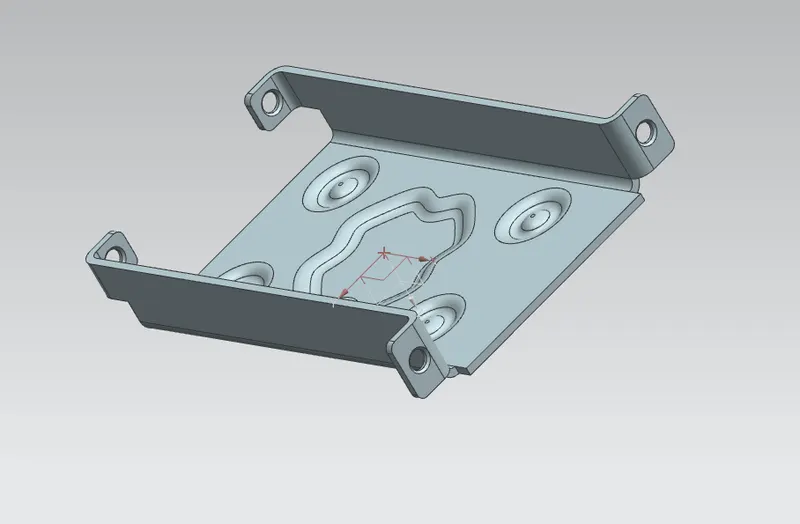
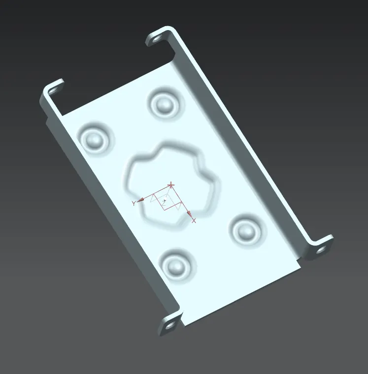
Isometric view
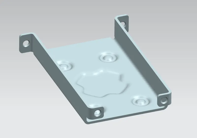
Final Casing Sheetmetal
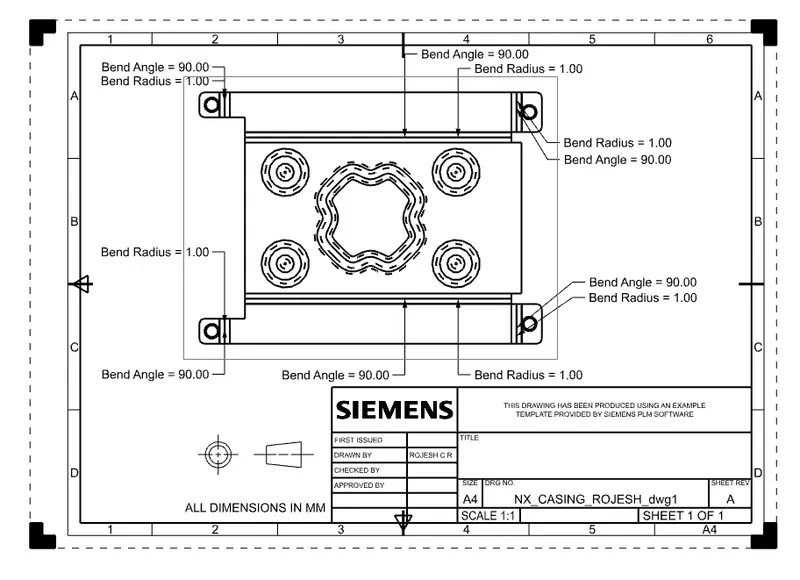
Drafting the Casing component.
CONCLUSION:
The sheetmetal component of Casing was created and explained in detail report of modelling the component.Flatterned the model and Drafted, shown views of images.