Advanced Sheet Metal Casing Design Using NX Cad
Casing Design Using NX CAD
Objective: To design a Sheet Metal casing by using Siemens NX Sheet metal workbench.
Introduction:-
Sheet metal enclosures are fabricated by 'cold forming', where the metal is clamped and bent in machines called 'press brakes'. As a result, metal typically cannot be formed into a true 90 degree corner. Instead, the corners are curved. You’ll find them in everything from junction boxes to control panels for industrial machinery. These enclosures are simple, versatile and extremely tough, so they’re in high demand for electrical projects and are often custom-fabricated.
Design Methodology
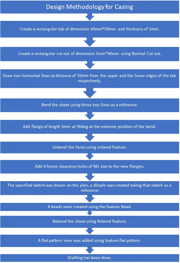
DESCRIPTION
SKETCH - It is a basic layout of any design.
TAB - It is used to create base feature of a sheet metal.
FLANGE - It is used to create a extended part of a sheet metal.
UNBEND - This feature is used to unbend the sheet metal taking any one face as a stationary face.
MIRROR FEATURE: It is used to mirror a feature across a plane. Here the features such as beads were mirrored using this tool.
REBEND - used to re bend the sheet metal.
DIMPLE - Used to create pitch up or pitch down surface.
BEAD-Used for giving strength to the sheet metal.
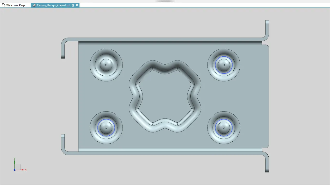
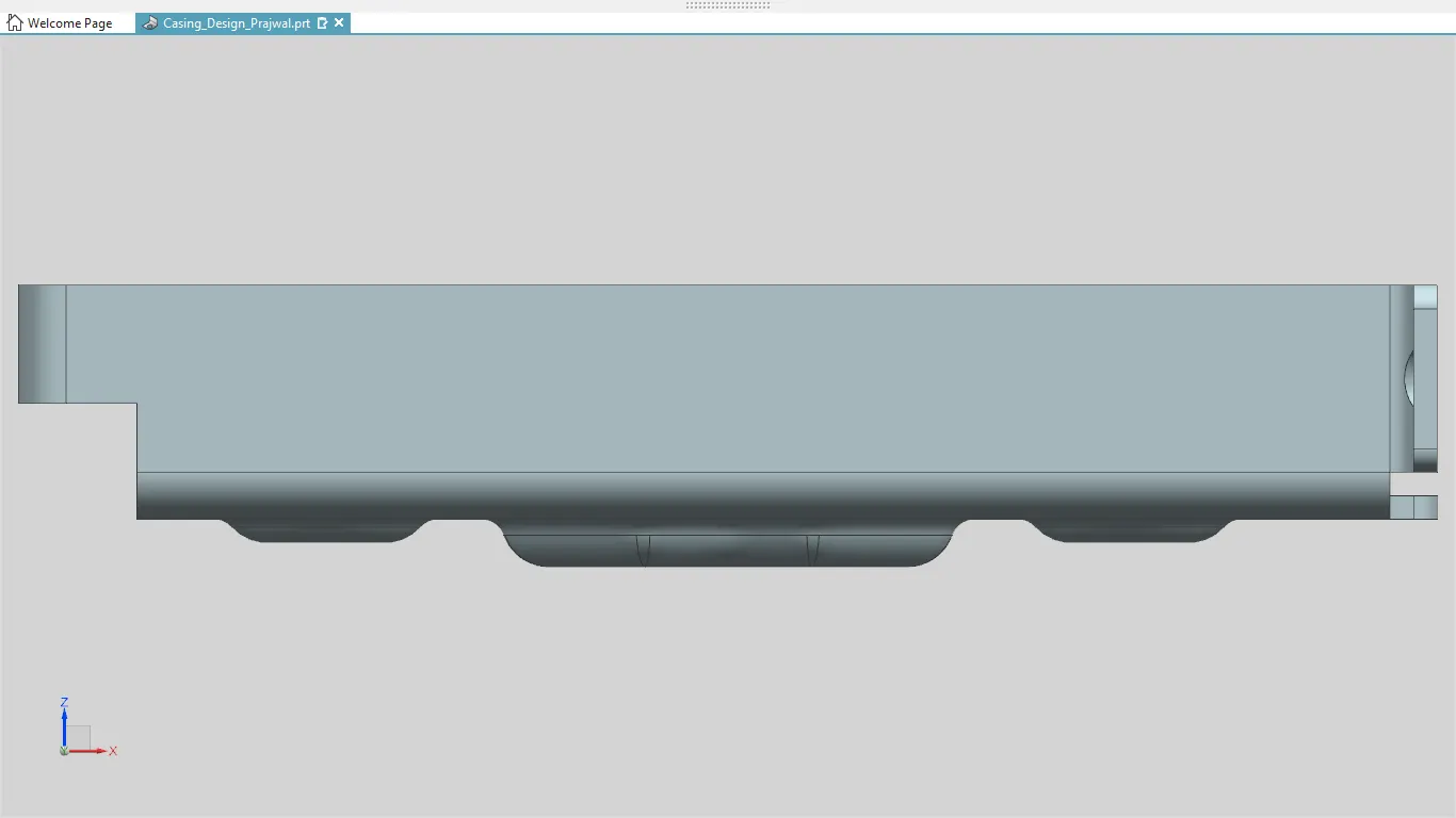
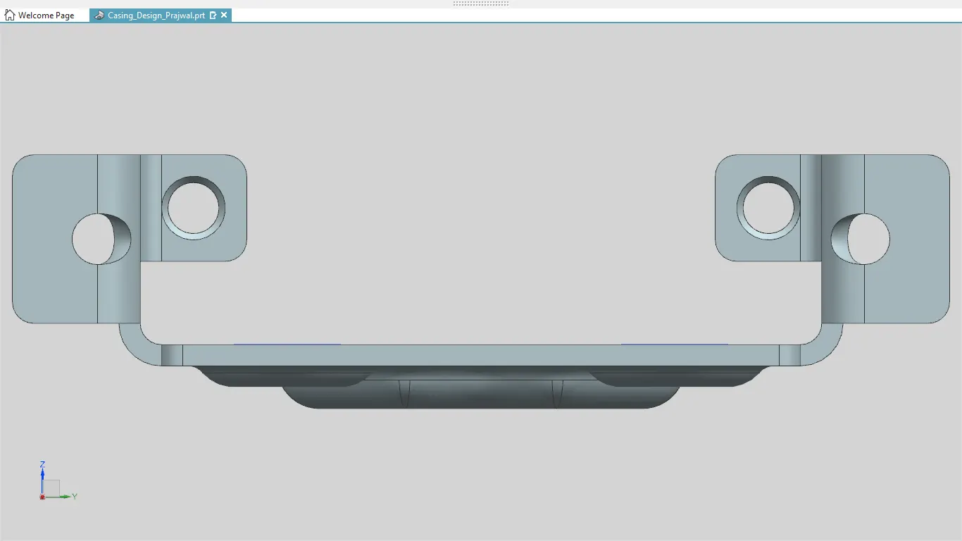
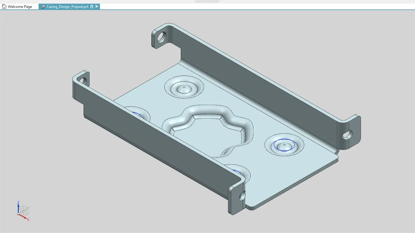
IMAGES OF THE MODEL
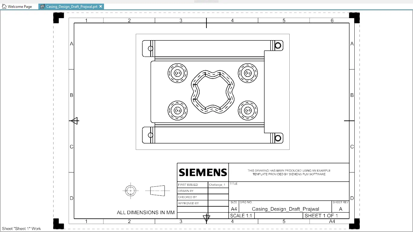
DRAWING SHEET IMAGE
CONCLUSION:
This being the first design in NX gave me an insight the use basic features like flange, tab, break corner, dimple, unbend, rebend and drafting, etc.
LINK OF THE MODEL
https://drive.google.com/drive/folders/1Rm-X90ClHZ40WEL6kVEV9S3mm29jn1-c?usp=sharing