Advanced Sheet Metal Box Assembly Design Using NX Cad
Sheet Metal Box Assembly Using NX CAD
Objective: To design a Sheet Metal Box Assembly by using Siemens NX Sheet metal workbench.
Introduction:-
Sheet metal enclosures are fabricated by 'cold forming', where the metal is clamped and bent in machines called 'press brakes'. As a result, metal typically cannot be formed into a true 90 degree corner. Instead, the corners are curved. You’ll find them in everything from junction boxes to control panels for industrial machinery. These enclosures are simple, versatile and extremely tough, so they’re in high demand for electrical projects and are often custom-fabricated.
Design Methodology
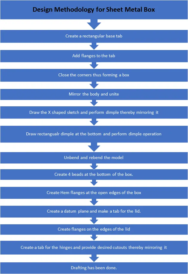
DESCRIPTION
Sketch: Sketch tool was used for creating the sketch required for tabs, cut outs, dimples, beads etc.
Tab: Tab is the base feature of sheet metal modelling. Tab is created by extruding a sketch along a vector by adding a thickness value.
Hem flange: This feature is used to fold the sheet metal flange back to the body itself. It was applied on the edges of box assembly for safe handling. It also improves the toughness of edges and prevent the damages that may occur to the edges of the box.
Flange: A flange is an external or internal ridge. Flanges were used to create the side walls of the box as well as hinges.
Dimple: Dimples are used to lift the material according to a sketch that simulates a stamping tool.
Bead: Beads are used to enhance the strength of the sheet metal part. It lifts the material according to a sketch that simulates a stamping tool. Here, four beads were used at the bottom of the box assembly.
Mirror body: It is used to mirror an existing body across a plane.
Mirror feature: It is used to mirror a feature across a plane. Here the features such as beads were mirrored using this tool.
Normal cut out: This tool is used to cut the material by projecting a sketch onto the model and then cutting normal to the faces intersected by the projection.
Unbend: This feature is used to unbend the adjacent bends and flatten them.
Rebend:It is used to rebend the unbended corners after adding any features on the faces.
Closed corner : Used to close the corner where two adjacent flanges meet by extending the bends and flanges. It eliminates the gap between adjacent flanges which were used to create walls of the box assembly.
Break corner : It is used to round or chamfer the sharp corners of a tab or flange.
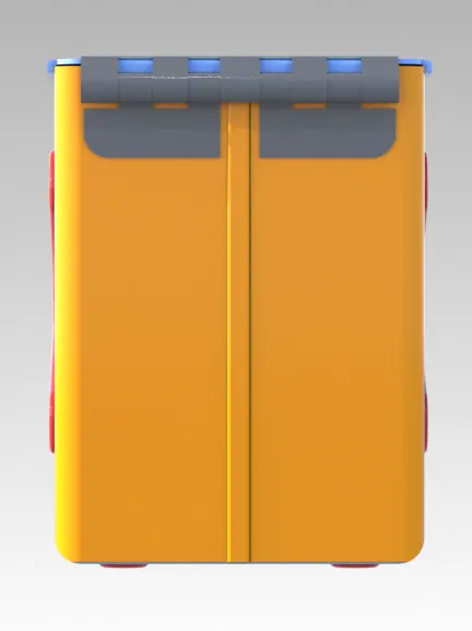
IMAGES OF THE MODEL
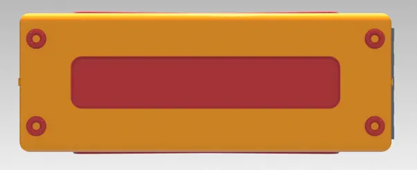
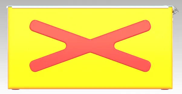
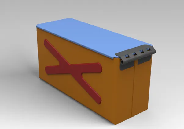
CONCLUSION:
This project underlines the tools and considerations for designing a sheet metal box assembly. It also underlines sheet metal application in NX and advantage of NX as a software for sheet metal design and its application as box assembly.
LINK OF THE MODEL
https://drive.google.com/drive/folders/1SmkFzX0Q8cy7Aciz5TX5MnJtoSvX05dP?usp=sharing