Advanced Sheet Metal Design Using NX Cad Challenge_1_Casing Design
TITLE:SHEET METAL CASING DESIGN USING NX CAD
OBJECTIVE:
To design a sheet metal casing using NX CAD
INTRODUCTION:
In this project we are gonna design a sheetmetal casing with NX CAD on sheetmetal workbench.NX is advanced CAD(COMPUTER AIDED DESIGN),CAE(COMPUTER AIDED ENGINEERING),CAM(COMPUTER AIDED MODELLING).The software performs in DESIGN(parametric and direct solid/surface modelling).
DESIGN METHODOLOGY:
DESCRIPTION:
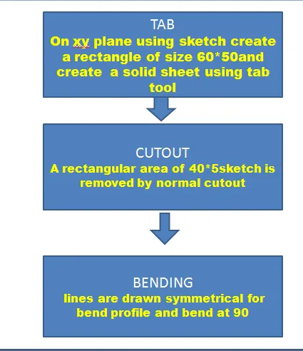
- TAB-It creates the sheet metal of preferred thickness.Create a sketch of rectangle and select TAB to create a sheet metal.
- CUTOUT-Cuts out a section of part with reference to a sketch.
- BENDING-Creating a reference line for bending action which acts as the bend angle for the sheet metal.Select BEND tool after the reference sketch lines and using the lines as reference create bend.
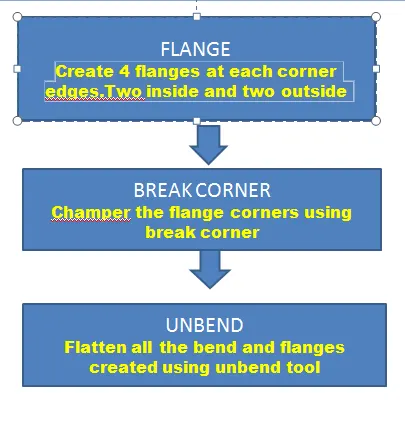
- FLANGE-Used to create falnge from the stationary part and bends between both creates and bend flange.
- BREAK CORNER-Rounds or chamfers sharp corner edges of flange or tab.Select the tool BREAK CORNER and just click the edges to be chamfered.
- UNBEND-Unbend all the flanges and bends created in a progressive form to repeat in REBEND.
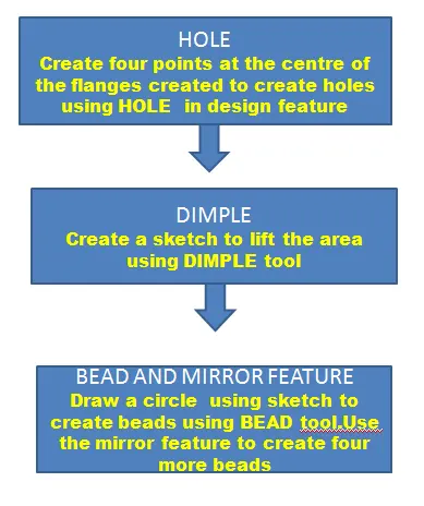
- HOLE-Under design feature more there is HOLE tool which adds hole to any part with preferred type and specfication of holes.
- DIMPLE -A tool for stamping feature which represents on a curve sketch for reference.It lifts the material through the sketch marking as stamping feature.
- BEAD-Another stamping tool features the lifting of material with sketch along the contour.
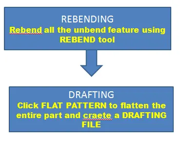
- REBEND-Restores the UNBEND feature along with the bend in the reverse progressive manner of the UNBEND with representing the stationary face or tab.
VIEWS:
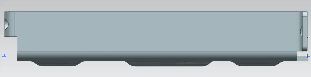
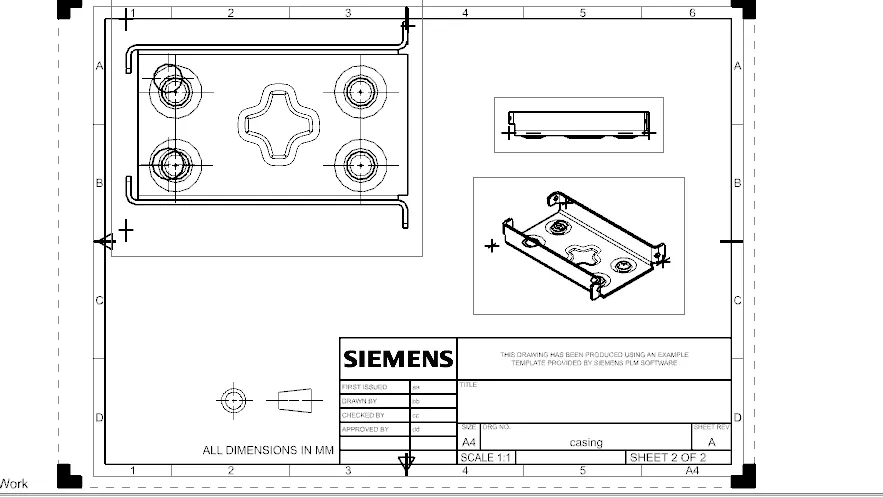
ISOMETRIC VIEW
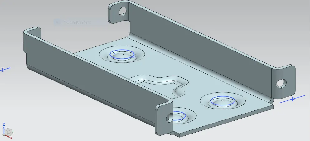
TOP VIEW
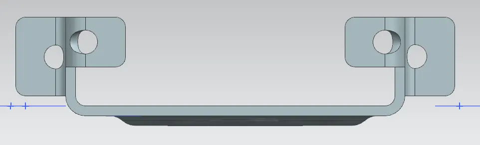
FRONT VIEW
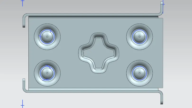
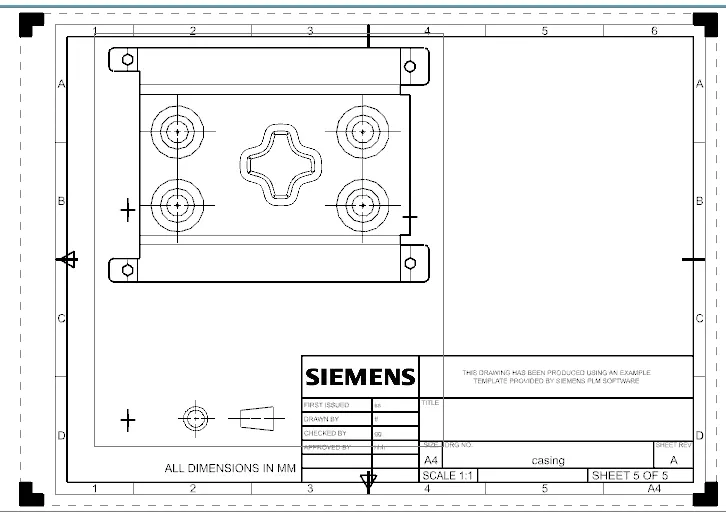
DRAFTING SHEET
CONCLUSION:
In the NX CAD by the tools and features of the sheet metal workbench SKETCH,TAB,NORMAL CUTOUT,BEND,FLANGE,BREAK CORNER,UNBEND,HOLE,DIMPLE,BEAD,REBEND ,DRAFTING we conclude the SHEET METAL CASING DESIGN