Advanced Sheet Metal Design Using NX Cad Challenge_1_Casing Design
TITLE:
Casing Design
Objective:
To design a Sheetmetal Casing using Siemens NX sheet metal application, and to get familiar about the usage of tools while designing.
Introduction:
A Casing is a sheet metal component used as a cover or a shell that protects the parts inside in it. It can be cut and bent into variety of shapes. It is created by the NX sheet metal application.
Design Methodology:
Below flowchart explains Features used while designing.
- Tab This command is used to create a base feature by extruding a sketchalong a vector by a thickness value, and by adding to existing faces and bend regions.
- Flange we can use this command to add a flat flange at an angle to a planar face and add a bend between two . it consists of bend and web region.
- Normal cutout It cuts the model perpendicular to the sketch.
- Bend It modifies the model by bending the material on one side of a sketch of a sketch line adding a bend between the two sides.
- Break corner It rounds the corners.
- Unbend It flattens the bend.
- Rebend It restores the material from the unbend.
- Hole It creates a hole from the sketch.
- Bead It lifts a material along a counter of sketch, that simulates stamping a tool.
- Mirror It is used to create a same feature with respect to plane or sketch.
- Dimple Lifts an area of a model inside a sketch that simulates stamping a tool.
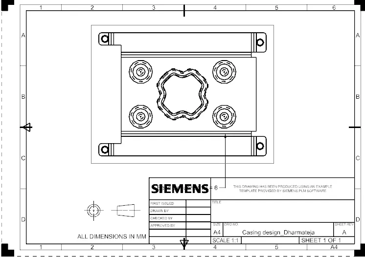
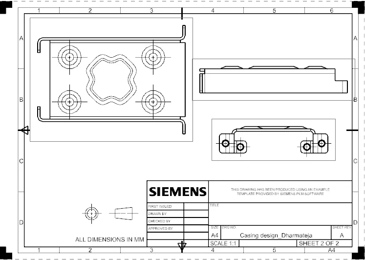
- Drafting It is creation of drawing for the purpose of knowing how the model is created.
Procedure:.
Step1: Initial design parameters such as material thickness, relief depth, bend radius and relief width for the sheetmetal is to be changed to 1mm.
Step2: The base feature of the casing is designed by drawing a2D sketch in the XY plane in the dimension of 60 and 50 in the region .
Step3: The feature tab is created with the help of 2D sketch drawn.
Step4: Then another sketch of rectangle is created on the xy plane with 5mm wide and 40 mm long with the edge coincide with the left end of the tab created previously and then feature cutout is performed with the sketch created.
Step5: A sketch is created again on the xy plane and it consists of 2 horizontal lines which is drawn parallel and symmetric about the X axis. The 2 line is located at 10mm from the upper and lower corners of the sheet metal.
Step6: the bending is formed by creating the sketch and the angle of bending is 90 deg for the both the lines.
Step7: The feature flange is performed with the length of 5mm. It is applied to 4 edges inside and outside based upon the procedure.
Step8: Then the feature break corner is applied to 16 sharp edges.
Step9: And unbend of the sheet metal is done by selecting the large face of the tab created for the reference and then the corresponding bend face.
Step10: The hole is created on same xy plane with the radius of 5mm on the surface of four unbends.
Step11: Sketch is created on same plane with the horizontal and vertical lines dimension of 5mm and it is mirrored of creating the same sketch.
Step12: The studio spline is created by selecting the 16 points in clockwise direction and the created spline is rotated about 45 deg from the origin.
Step13: Dimple is performed by selecting the curve and then the depth of the dimple is changed to 1mm.
Step14: To perform bead the sketch consists of four circles is created on the tab surface with the diameter of 5mm and then it is mirror according to the procedure.
Step15: The rebend is done by selecting the faces in the reverse order in which they bend.
Step16: The flat pattern is done by selecting the flat face of the sheetmetal for the reference.
Step17: For creating a drafting A4 size sheet is selected according to the procedure and then the created flat pattern is selected in the model view option and scale ratio is reduced to 2:1
Step18: Save the file.
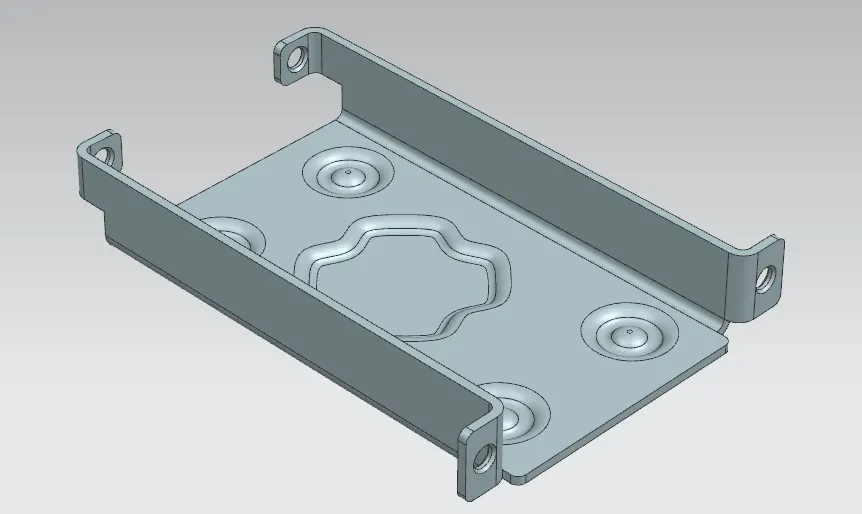
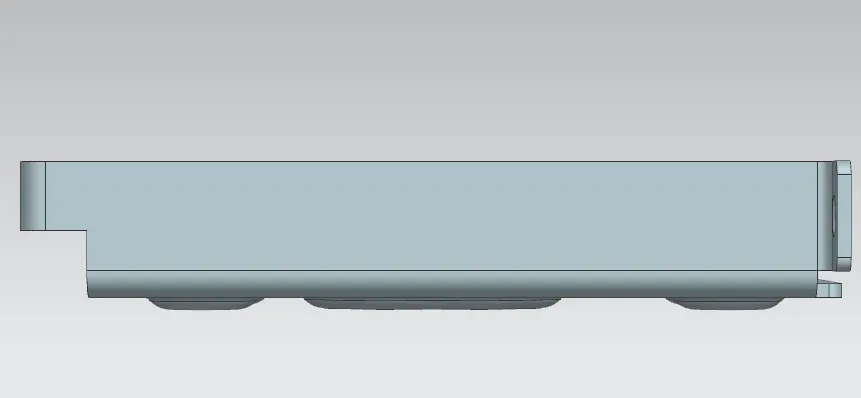
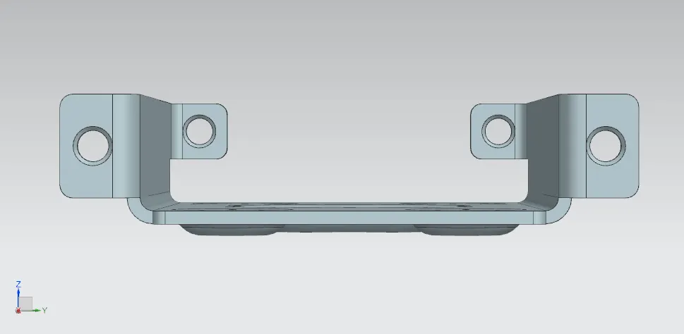
Different views of casing
Isometric view
Front view
Side view
Top view
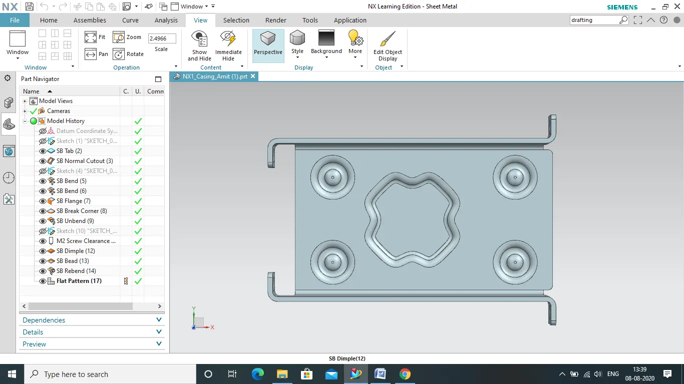
Drafting Images
Conclusion: Hence the design of sheet metal casing and drafting is performed.