Advance CFD Meshing of Ford for External Aerodynamics using ANSA
Advance Meshing of Ford for External Aerodynamics
I.Aim:
1.To perform Geometry cleanup , surface Meshing and Volumetric Meshing od Ford for external aerodynamics
2.To create wind tunnel and do tyre crushing with standard dimensions
II.Geometry Link :
Note : I was not able to perform volumetric meshing considering my laptop ability . Its i3 7th gen
Laptop was hanging while trying for volumetric meshing
https://drive.google.com/file/d/1ubrF3qEMlOVyoHehTKJSl_h4OOAYbYq-/view?usp=sharing
III.Procedure:
As we are going to perform this geometry cleanup and meshing for external aerodynamics we need to keep that in mind for the approach we are chosing . If we can closely observe the geometry we can find that it is a symmetric geometry . For that kind of geometries we can divide them into half and work on that half . After cleaning up that half by removing all of the errors , we can perform mirror operation and can create the complete error free model of the car.
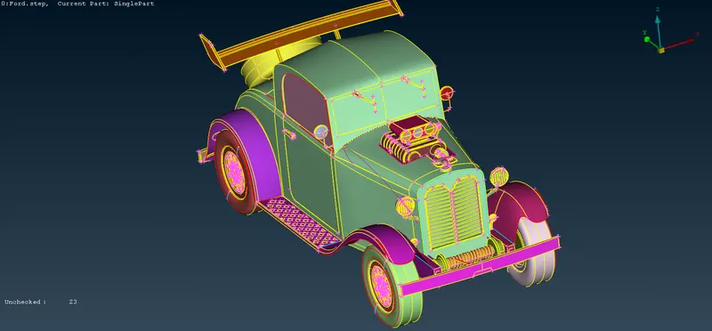
The order of processes which we are going to use are :
1. Geometry cleanup of half part
2.Mirroring of that part
3.creation of wind tunnel and tyre crushing
4. Surface meshing
5.Volume meshing
IV. Geometry cleanup of Half Part :
1.First of all we need to check the units whether those are in mm or not
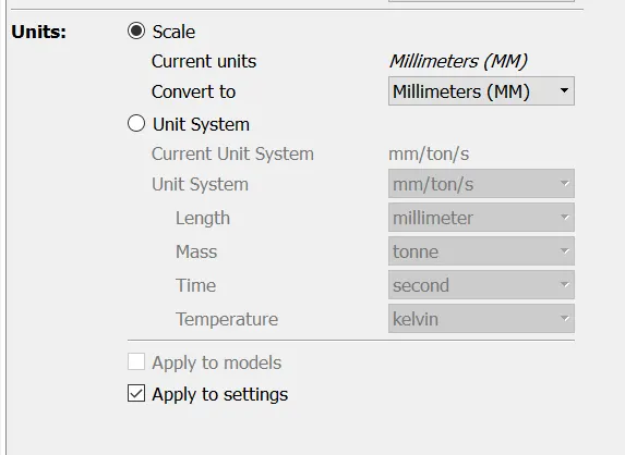
2.Resolution seems to be fine
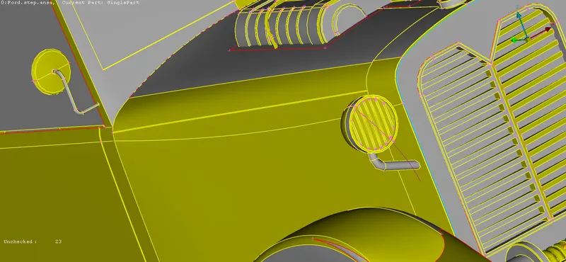
3.We will set orientation to grey outside and yellow inside .
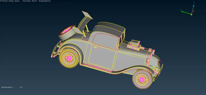
4.The approach we are going to take for the cleanup of this particular model is , as the geometry is symmetric , we are going to hide the unsymmetric parts and we will be making the other symmetric part as half . We delete one half and we clean the remaining half and we will mirror the same to get the complete the model .
5.These are parts which can be equally divided into half :the car is symmetric about Z axis . Here the parts mentioned below are evenly spread with respect to Z axis .
- Underbody
- Exterior
- Headlamp
- Upper wing
- Rear fender
- Rear Bumper
- Front Bumper
- Rope cable
- Pulling motor
- Connecting wire
- Horn
- Wheels
- Exterior Faces
- Side Glass
- Wind shield wiper
- Side mirror
- Side Handle
- Back Handle
- Rear Lights
6. These are the parts that are unsymmetric in the car.As the car is symmetric about Z axis , these below mentioned parts are either one side of the car.
- Hook and sweep
- Flying Macos
- Engine
- Instrument cluster
- Key Holder
- Speedometer odometer
- Steering wheel
- Seat
- Stepine
7. Now we will hide all the unsymmetric parts and lock the geometry with symmetric parts along with the radiator because we are going to assign that as porus media at the type of assigning materials during analysis.
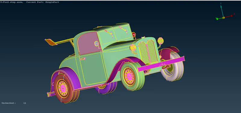
8. Now we divide the entire geometry into half by using Plane cut option
9.Steering ,instrument cluster , seat are not going to perform in external aerodynamic simulation we need not to keep them so we can delete them. Those are not going to interract with the external air flow around the car
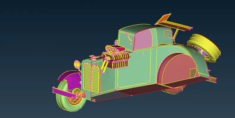
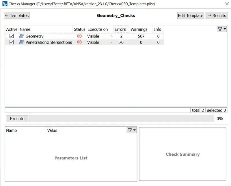
9.Initial error chek :
10. We clean the mirror and its surroundings :
there is one overlapping between the mirror face and the external body face that face has to be deleted so that we can see the other side of the mirror
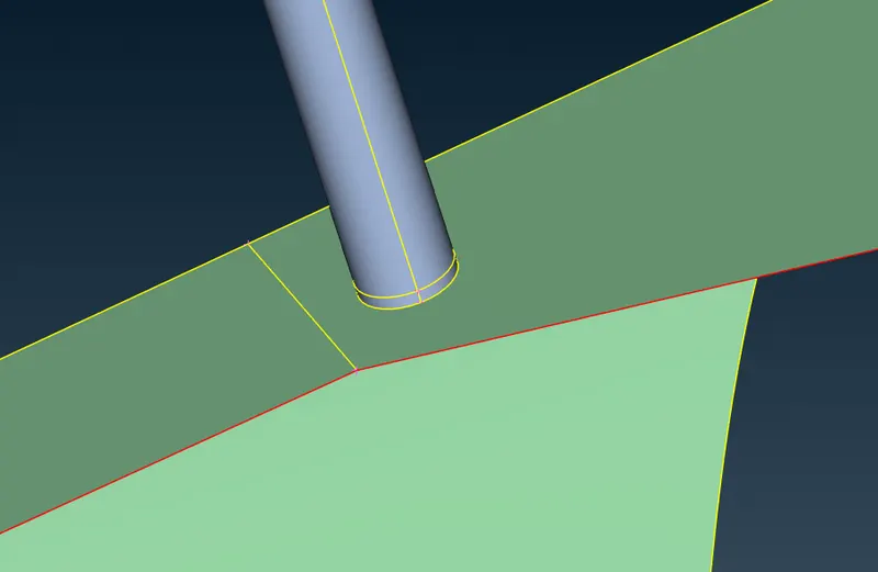
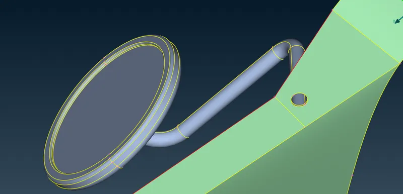
that overlapping has been removed
11. Cleaning of Tyres:
Tyres can also be mirrored ,That means we can clean one tyre and mirror or copy that tyre to another location
i.Tyres are isolated
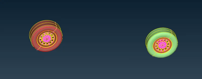
ii. In order to clean the geometry of the tyres , we first clean one of the tyre geometry and after that we will proceed with pasting the that geometry .
iii. To copy and proceed further, we will be wanting one reference point .
We will be creating one 3D points on COG
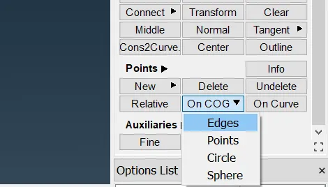
3D Point has been created 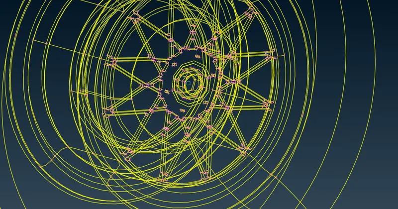
In the same manner it has been done for the second tyre also
Other tyre has been deleted
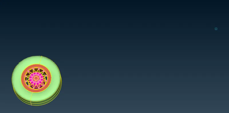
Now we can start the cleaning of the tyre
As we are cleaning this for external aerodynamics , we are not going to be using the faces which are in the internal part of the tyre . we study the PID and will remove the PID which are not going to interract with the flow
Those can be deleted
Initial check on tyres:
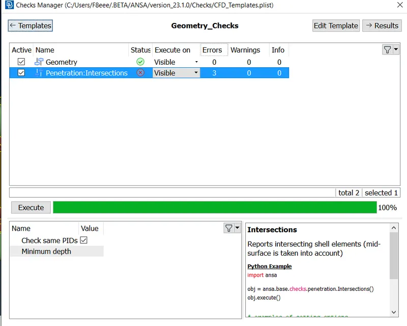
Errors in tyres can be removed by clearing the intersection error between the faces of tyres 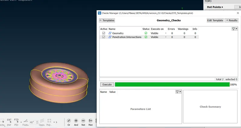
The cleaned tyre mirrored to the other side by creating the 3D points and taking it as reference .
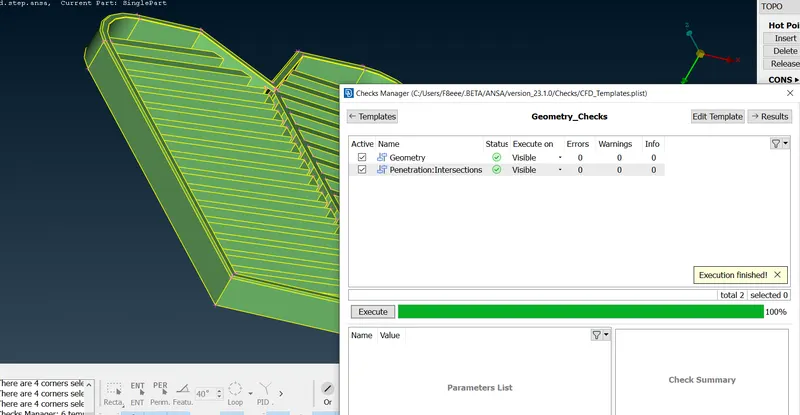
Cleaning of Grill :
unnecessary Hot points have been deleted
Grill have been isolated and initial error check has beendone
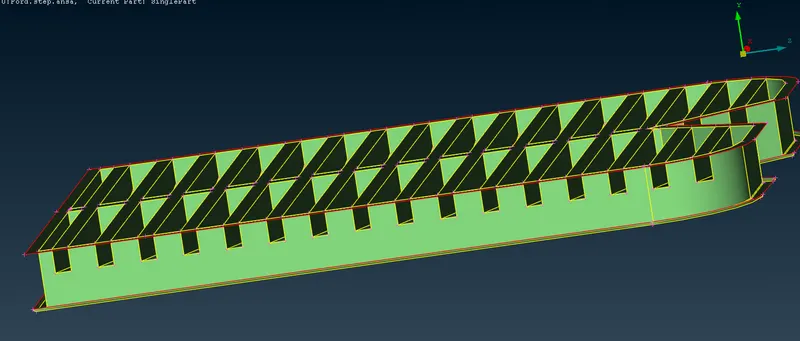
the faces that we can see above in the side are overlapped between grill case and the straps , those straps were removed by projecting the same cons on to the surface and deleting the faces .
grill is made free of any error :
Cleaning of Exterior body :
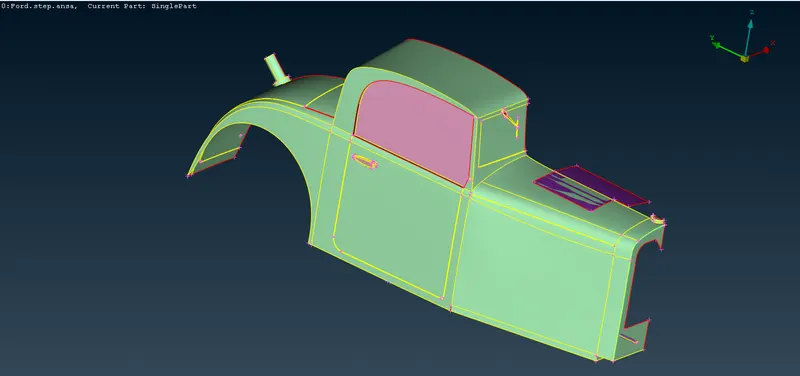
Where there are overlapping faces there the cons have been projected using cons project option , and the as the internal parts of the car are not going to be interracting with the air flow , we will not be keeping them for analysis .
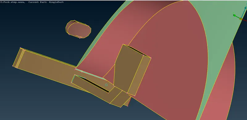
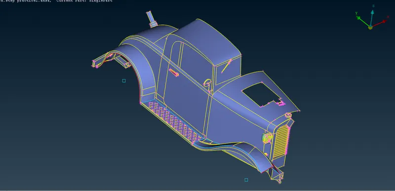
Error check has been performed on the parts till now :
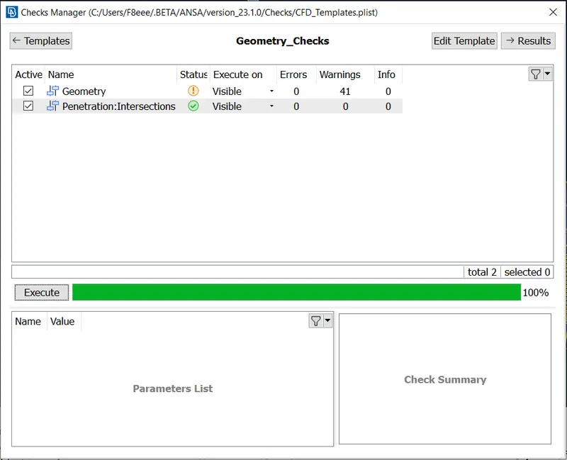
Errors that are formed are single cons which are by due to hiding of half of the part . Those can be removed by adding another half part of the exterior by mirroring .
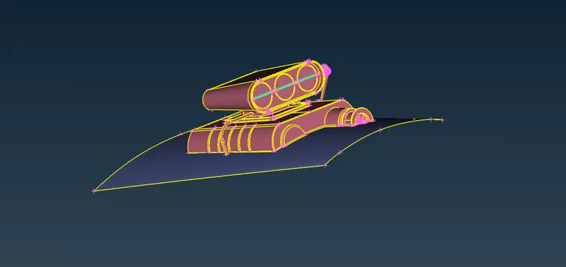
Half of the part of the below part is not going to interract with the flow so these parts can be deleted it made error free
Stepnie tyre also made free of errors :
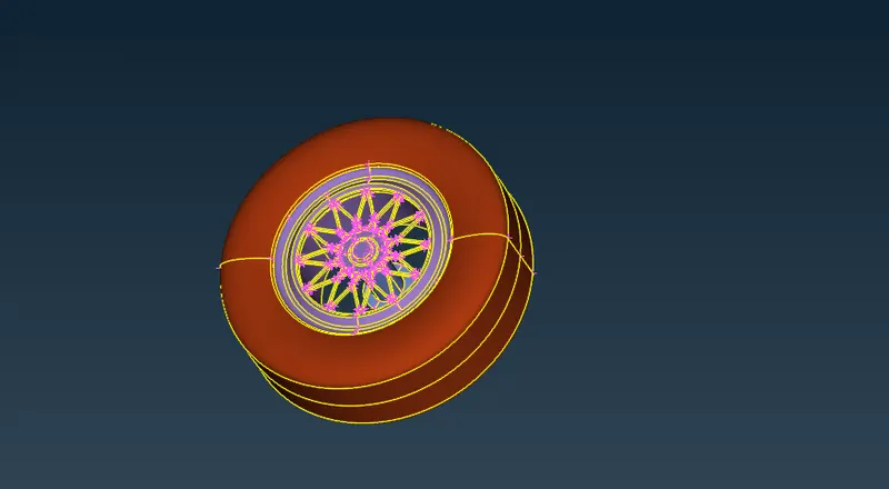
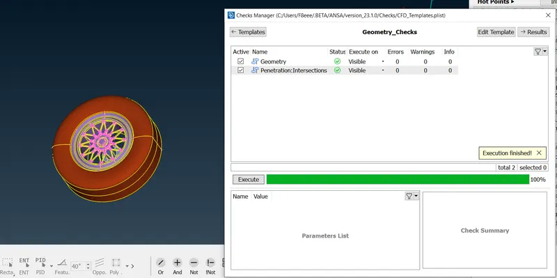
Now the all of the external parts which are exposed to the external air are cleared out of errors .
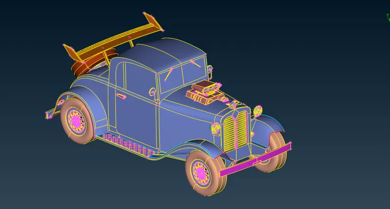
Half of the parts which are cleared out of all the intersection errors are now mirrored and the entire CAR has been formed like the above .
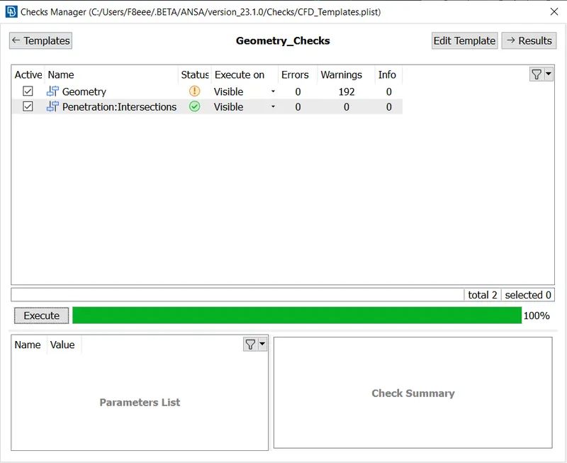
Now we have to create wind tunnel and perform tyre crushing .
PIDs assigned for the entire car model according to the convenience
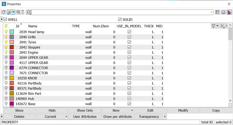
Now we have to perform tyre crushing and windtunnel creation .Wind tunnel is the specific region where we are going to study the interraction of air and the car body . It depends on the size of the automobile . It should be as such that it should not be affecting the results .
Dimensions of the wind tunnel :
Dimensions play vital role in terms of getting proper result of our solution . Lets assume
x-Length of car
y-Width of car
h-height of car
then the dimensions of the wind tunnel must be
3x infront of car,6x back of the car
it should be x distance in both of the sides of the car
4h above the car ,and it should be such a way that it was laying on the road . for that only we are going to do tyre crushing.
For the geometry we are considering , Length of the car x=3424.14 mm approximately x=3500mm
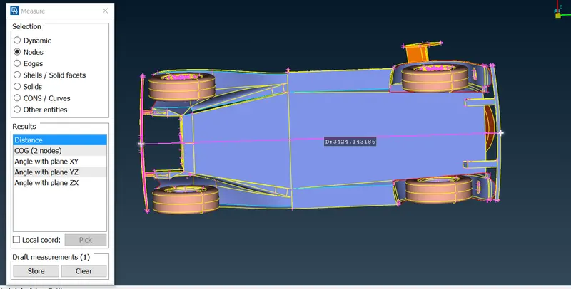
Measuring height : (slant)h=2049.18 Approximately h= 2000mm
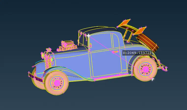
Creation of Windtunnel :
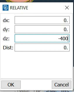
We create one face at the bottom in 400mm
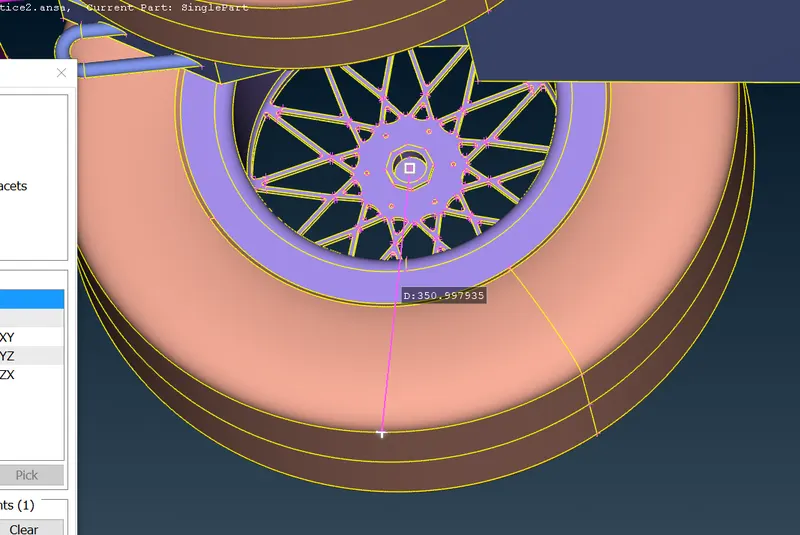
Rear face of wind tunnel is 6x so 6*3500 = 21000+500 = 21,500mm
Front face of wind tunnel 3x = 3*3500 = 10,500 = 500= 11,000mm
Side faces of winf tunnel x = 3500 mm
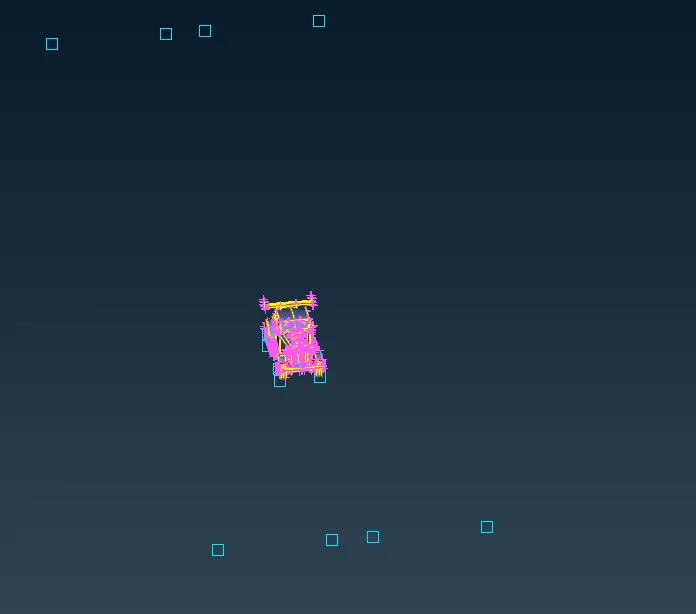
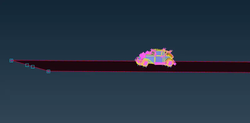
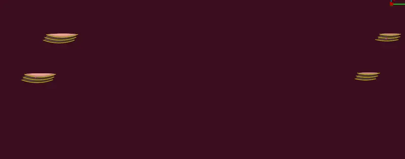
Tyre crushing has been performed on the car tyres
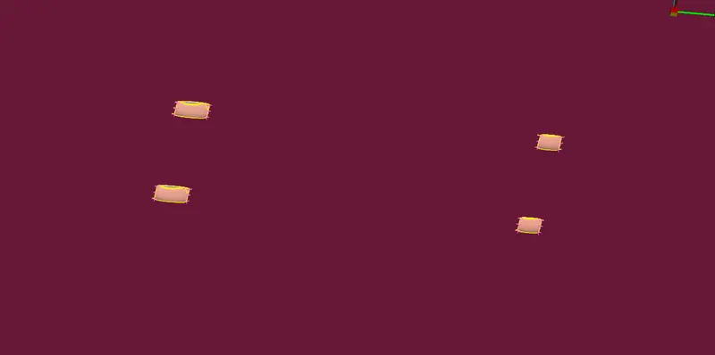
The faces which are in between the tyre faces and bottom face of wind tunnel have been deleted using the faces intersect option , so as to create the situation same as the real .
As the height of the wind tunnel should be 4h above the car
h is 2000mm that means the top face of the wind tunnel should be 2000mm above the car. so the height of the top face of wind tunnel would be 5h from the bottom face of the wind tunnel . so the height of the wind tunnel in our case would be 5h 10,000mm approximately
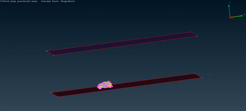
All sides have been created
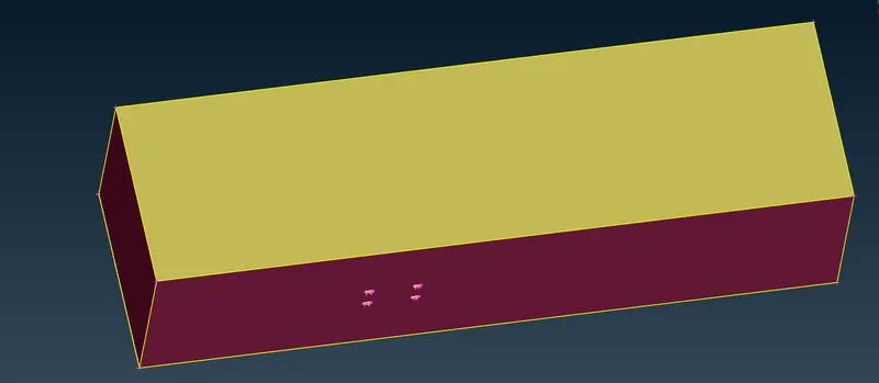
Now the creation of windtunnel has been over. Now we will be going for meshing process.
Meshing :
Our geometry should be free of any errors before proceeding further for meshing .So lets have a check :
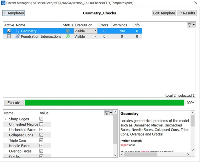
We will start meshing from tyres and after that we can go to grills and exteriors.
We will study the geometry and find the smallest length between the faces and we can measure it .
Meshing of tyres:
1. Tyres are isolated
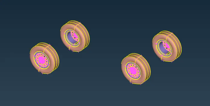
2. We will switch on quality criteria and consider a skewness value of 0.5 mm.
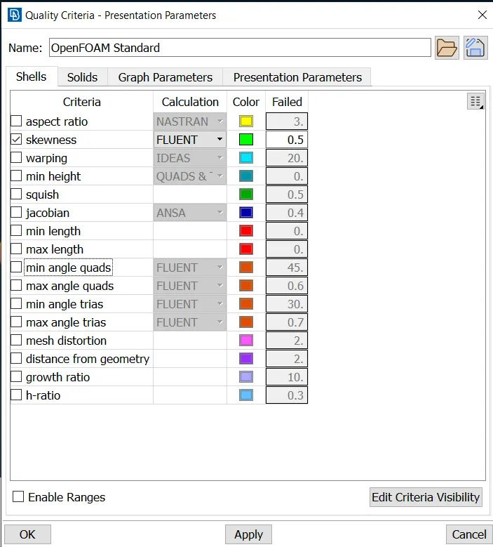
Smallest node length possible for the tyre is 3mm .
Auto CFD Spacing paremeters
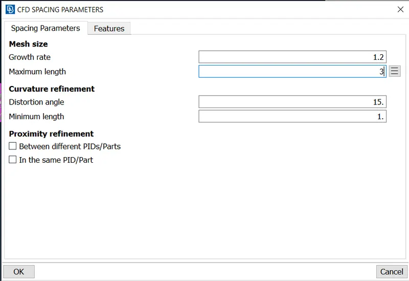
It is same given for macros also
we will use CFD Mesh generation for this challenge .
tyres have been meshed . 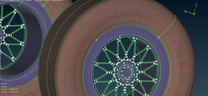
Meshing of grills :
CFD Spacing option for paremeters and macros
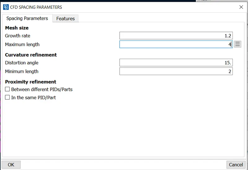
Grills have been meshed
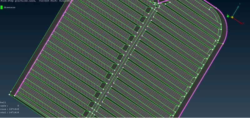
Meshing of exterior part
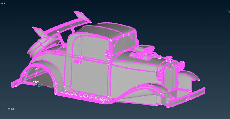
in meshing external parts we will seperate smaller parts and mesh them first later we can mesh remaining parts.
Exterior parts are meshed
Meshing of wind tunnel :
For bottom plate 400mm paremeter length
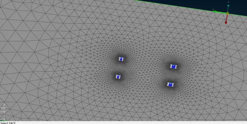
For top face 500mm paremeter length
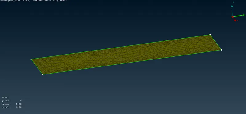
For meshing side faces we will use mannual spacing algoriothm :
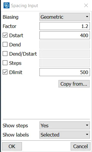
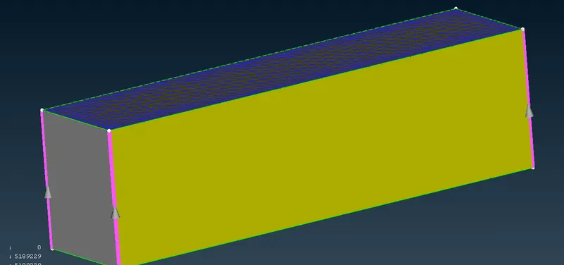
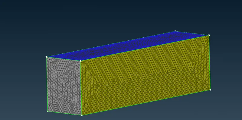
Side faces have been meshed
Volumetric Meshing :
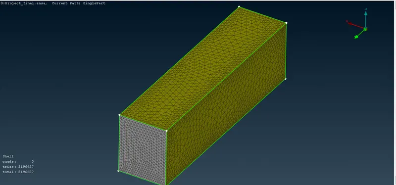
Volumetric meshing can be subjected to the system performance and the capabilities , My system is not that much capable enough to handle volumetric meshing