BlockMesh drill down challenge
Abstract:
In this problem, the analysis of transient solver for incompressible laminar flow of newtonian fluids is performed by OpenFOAM software tool.An initial Mathematical analysis of Reynolds No. is calculated to figure out the appropriate CFD codes to be used.OpenFOAM case file like the controlDict file and blockMeshdict file is modified to obtain the required result.
Aim:
1)To Generate the BlockMesh file using OpenFOAM and by using the icoFoam solver to simulate the flow through a backward facing step
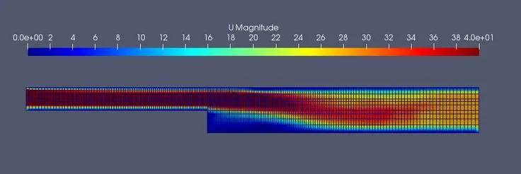
2)To compare the velocity magnitude contours near the step region for the mesh grading factor of 0.2,0.5,0.8.
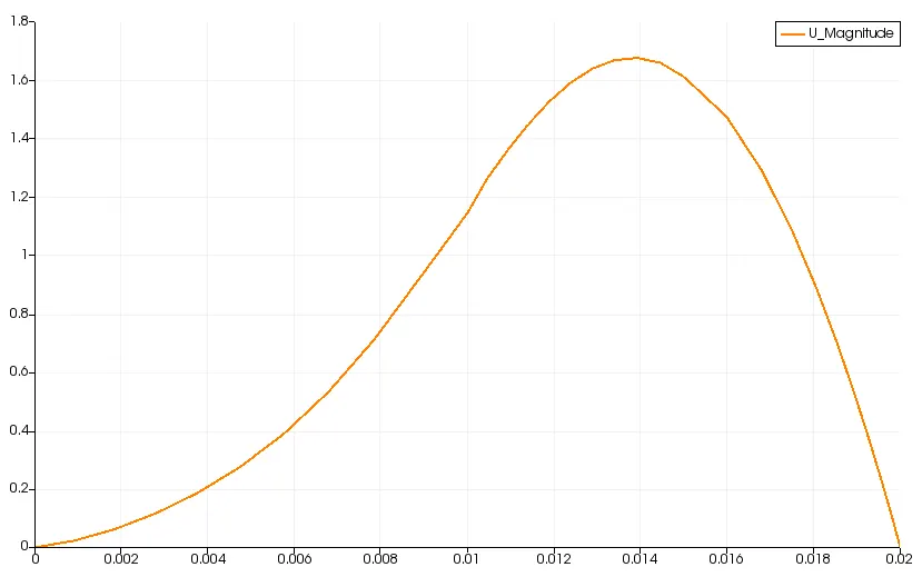
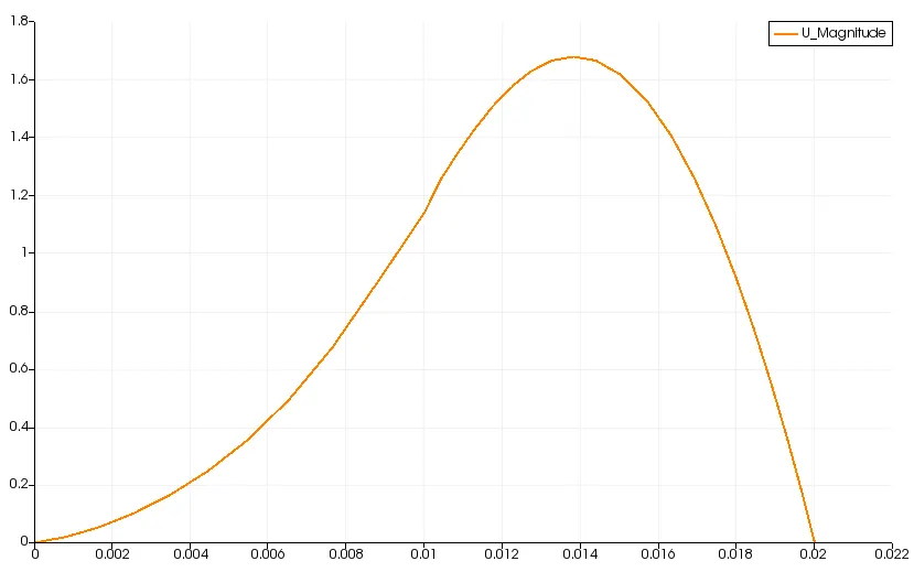
3)After the simulation by icoFoam solver, the results are opened in paraview and the results are post processed like velocity profile near the step zone and to check the effect of Grading scheme on velocity profile.
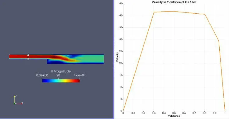
4) to measure the velocity profile at a distance of 0.085 m from the inlet of the geometry.
Problem Description:
Fluid flow analysis has to be performed through the given cavity as shown.
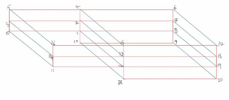
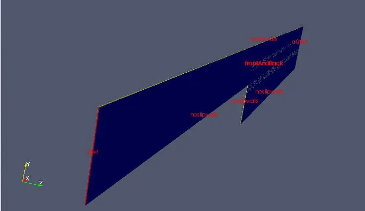
The velocity at a point 0.085 meters from the inlet has to be determined.The mesh grid size has to be changed such that the finer mesh are created at the boundaries.(grid size: 0.3, 0.5 and 0.8).variation of velocity along the cavity for each grid sizes are needed to be plotted and discussed.
The number of cells along the x-axis(longer dimension)=200
The number of cells along the y-axis =10
Boundary Conditions:
- Inlet velocity is 1m/s.
- The exit pressure is atmospheric
- All the boundary fluid layer is stick to the solid surface and the velocity at the solid durface is zero.
- Fully developed flow at the exit.
Here in the task cavity case from the icoFoam solver which is part of the incompressible tutorials is copied to run folder and BlockMeshdict file is edited to get the required shape in OpenFOAM.
After editing the blockMesh dict file,blockMesh command is run in the case setup to generate shape in OpenFOAM. Once after obtaining the required geometry icoFoam solver is used to run the simulation.After the simulation ran. parafoam is ran in the command for the post processing to be done in paraview simulation where the geometry is viewed with final results.
Different mesh grading factor is used in the process
OpenFOAM code organization:
Assumptions to be considered in the analysis are:
- Newtonian fluid-obeys Newtons law of viscosity
- Flow is incompressible-There is no density change taking place throoughout the flow domain.Mach No. is less than 3.
- Velocity at the inlet is 1m/s.`Re = (rho*v*D)/(mu)=(1xx1xx0.01)/(1.868xx10^-5)=536`.Hence Laminar Flow.
- 2D Flow
IcoFoam solver is used in OpenFoam as code organization which is in the incompressible section..
controlDict file:
/*--------------------------------*- C++ -*----------------------------------*\\
  =========                 |
  \\\\      /  F ield         | OpenFOAM: The Open Source CFD Toolbox
   \\\\    /   O peration     | Website:  https://openfoam.org
    \\\\  /    A nd           | Version:  6
     \\\\/     M anipulation  |
\\*---------------------------------------------------------------------------*/
FoamFile
{
    version     2.0;
    format      ascii;
    class       dictionary;
    location    \"system\";
    object      controlDict;
}
// * * * * * * * * * * * * * * * * * * * * * * * * * * * * * * * * * * * * * //

application     simpleFoam;

startFrom       startTime;

startTime       0;

stopAt          endTime;

endTime         0.056666;

deltaT          10e-7;

writeControl    timeStep;

writeInterval   20;

purgeWrite      0;

writeFormat     ascii;

writePrecision  6;

writeCompression off;

timeFormat      general;

timePrecision   6;

runTimeModifiable true;


// ************************************************************************* //
BlockMesh dict file:
/*--------------------------------*- C++ -*----------------------------------*\\
  =========                 |
  \\\\      /  F ield         | OpenFOAM: The Open Source CFD Toolbox
   \\\\    /   O peration     | Website:  https://openfoam.org
    \\\\  /    A nd           | Version:  6
     \\\\/     M anipulation  |
\\*---------------------------------------------------------------------------*/
FoamFile
{
    version     2.0;
    format      ascii;
    class       dictionary;
    object      blockMeshDict;
}
// * * * * * * * * * * * * * * * * * * * * * * * * * * * * * * * * * * * * * //

convertToMeters 0.01;

vertices
(
 (0 0 0)// point 0
 (8 0 0)// point 1
 (8 0.5 0)// point 2
 (0 0.5 0)// point 3
 (0 1 0)// point 4
 (8 1 0)// point 5
 (20 1 0)// point 6
 (20 0.5 0)// point 7
 (20 0 0)// point 8
 (20 -1 0)// point 9
 (8 -1 0)// point 10
 (8 0 0.05)// point 11
 (0 0 0.05)// point 12
 (0 0.5 0.05)// point 13
 (8 0.5 0.05)// point 14
 (8 1 0.05)// point 15
 (0 1 0.05)// point 16
 (20 1 0.05)// point 17
 (20 0.5 0.05)// point 18
 (20 0 0.05)// point 19
 (20 -1 0.05)// point 20
 (8 -1 0.05)// point 21

);


blocks
(
    hex (0 1 2 3 12 11 14 13)
    (200 10 1)
    simpleGrading (0.5 1.5 1)

    hex (3 2 5 4 13 14 15 16)
    (200 10 1)
    simpleGrading (0.5 0.5 1)

    hex (2 7 6 5 14 18 17 15)
    (200 10 1)
    simpleGrading (1.5 0.5 1)

    hex (1 8 7 2 11 19 18 14)
    (200 10 1)
    simpleGrading (1.5 1.5 1)

    hex (10 9 8 1 21 20 19 11)
    (200 10 1)
    simpleGrading (1.5 1.5 1)
);

edges
(
);

boundary
(
    inlet
    {
        type patch;
        faces
        (
            (12 0 3 13)
            (13 3 4 16)
        );
    }
    outlet
    {
        type patch;
        faces
        (
            (17 18 7 6)
            (18 19 8 7)
            (19 20 9 8)
        );
    }
    front
    {
        type empty;
        faces
        (
            (12 11 14 13)
            (13 14 15 16)
            (14 18 17 15)
            (11 19 18 14)
            (21 20 19 11)
        );
    }
    back
    {
        type empty;
        faces
        (
            (0 1 2 3)
            (3 2 5 4)
            (2 7 6 5)
            (10 9 8 1)
        );
    }
    topandbottom
    {
        type wall;
        faces
        (
            (12 11 1 0)
            (1 10 21 11)
            (21 20 9 10)
            (4 5 15 16)
            (5 6 17 15)

        );
    }
);

mergePatchPairs
(
);

// ************************************************************************* //
After this, next step is to give Boundary conditions.The Boundary conditions for pressure and velocity are given in the 0 folder.
Initial conditions for velocity.
/*--------------------------------*- C++ -*----------------------------------*\\
  =========                 |
  \\\\      /  F ield         | OpenFOAM: The Open Source CFD Toolbox
   \\\\    /   O peration     | Website:  https://openfoam.org
    \\\\  /    A nd           | Version:  6
     \\\\/     M anipulation  |
\\*---------------------------------------------------------------------------*/
FoamFile
{
    version     2.0;
    format      ascii;
    class       volVectorField;
    object      U;
}
// * * * * * * * * * * * * * * * * * * * * * * * * * * * * * * * * * * * * * //

dimensions      [0 1 -1 0 0 0 0];

internalField   uniform (0 0 0);

boundaryField
{
    inlet
    {
        type            fixedValue;
        value           uniform (1.5 0 0);
    }

    outlet
    {
        type            zeroGradient;
    }

    frontAndBack
    {
        type            empty;
    }
    topandbottom
    {
        type            noSlip;
    }
}

// ************************************************************************* //
Initial conditions for pressure.
/*--------------------------------*- C++ -*----------------------------------*\\
  =========                 |
  \\\\      /  F ield         | OpenFOAM: The Open Source CFD Toolbox
   \\\\    /   O peration     | Website:  https://openfoam.org
    \\\\  /    A nd           | Version:  6
     \\\\/     M anipulation  |
\\*---------------------------------------------------------------------------*/
FoamFile
{
    version     2.0;
    format      ascii;
    class       volScalarField;
    object      p;
}
// * * * * * * * * * * * * * * * * * * * * * * * * * * * * * * * * * * * * * //

dimensions      [0 2 -2 0 0 0 0];

internalField   uniform 0;

boundaryField
{
    inlet
    {
        type            zeroGradient;
    }

    outlet
    {
        type            fixedValue;
        value          uniform 0;
    }

    frontAndBack
    {
        type            empty;
    }
    topandbottom
    {
        type            zeroGradient;
    }
}

// ************************************************************************* //
Results and discussions:
Mesh Grading(BlockMesh geometry)
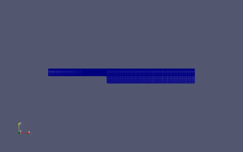
0.2 scaling
    hex (0 1 2 3 12 11 14 13)
    (200 10 1)
    simpleGrading (0.2 1.2 1)

    hex (3 2 5 4 13 14 15 16)
    (200 10 1)
    simpleGrading (0.2 0.2 1)

    hex (2 7 6 5 14 18 17 15)
    (200 10 1)
    simpleGrading (1.2 0.2 1)

    hex (1 8 7 2 11 19 18 14)
    (200 10 1)
    simpleGrading (1.2 1.2 1)

    hex (10 9 8 1 21 20 19 11)
    (200 10 1)
    simpleGrading (1.2 1.2 1)
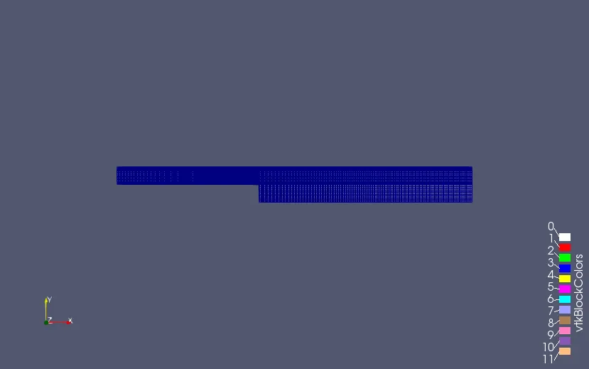
0.5 scaling
    hex (0 1 2 3 12 11 14 13)
    (200 10 1)
    simpleGrading (0.5 1.5 1)

    hex (3 2 5 4 13 14 15 16)
    (200 10 1)
    simpleGrading (0.5 0.5 1)

    hex (2 7 6 5 14 18 17 15)
    (200 10 1)
    simpleGrading (1.5 0.5 1)

    hex (1 8 7 2 11 19 18 14)
    (200 10 1)
    simpleGrading (1.5 1.5 1)

    hex (10 9 8 1 21 20 19 11)
    (200 10 1)
    simpleGrading (1.5 1.5 1)
0.8 scaling
hex (0 1 2 3 12 11 14 13)
    (200 10 1)
    simpleGrading (0.8 1.8 1)

    hex (3 2 5 4 13 14 15 16)
    (200 10 1)
    simpleGrading (0.8 0.8 1)

    hex (2 7 6 5 14 18 17 15)
    (200 10 1)
    simpleGrading (1.8 0.8 1)

    hex (1 8 7 2 11 19 18 14)
    (200 10 1)
    simpleGrading (1.8 1.8 1)

    hex (10 9 8 1 21 20 19 11)
    (200 10 1)
    simpleGrading (1.8 1.8 1)
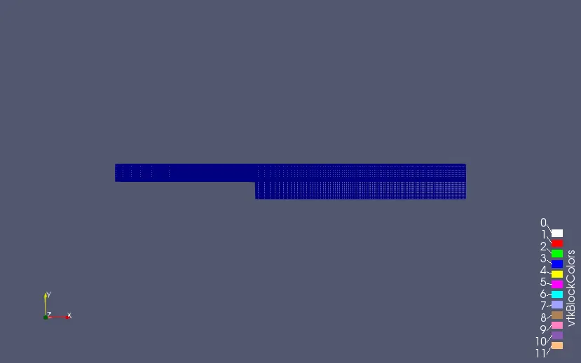
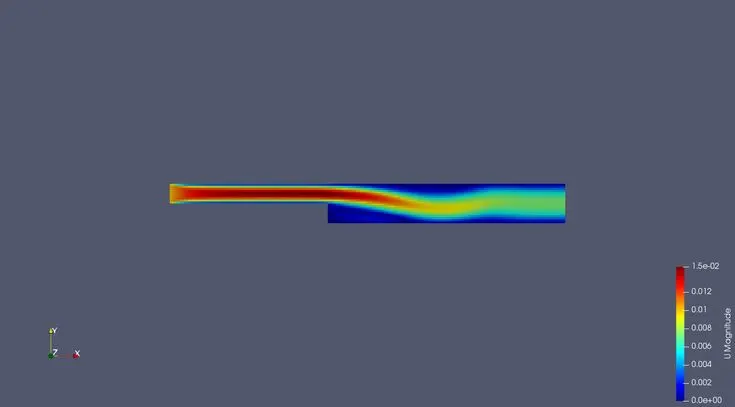
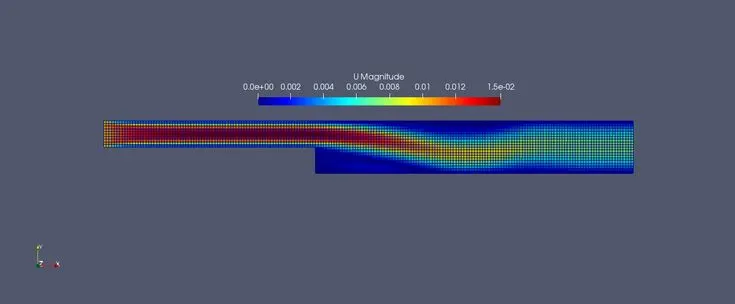
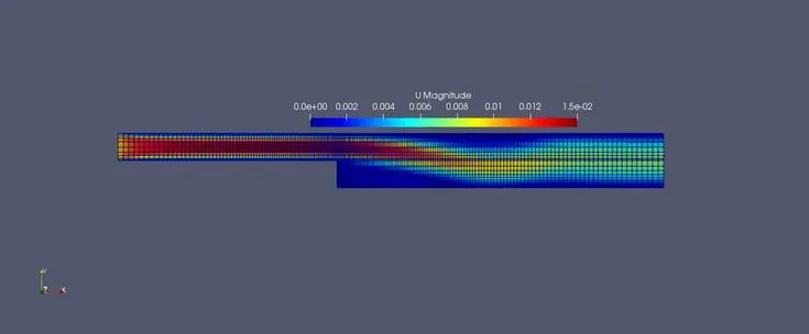
From the images attached which shows the different mesh gradings, we can see how the mesh grading looks at different grading factors.Depending on the factor used, the grid is much finer towards the outlet as compared to the step. the difference in the grading scheme affects the results depending on if the mesh size is much more coarse in the region of consideration.As we are reducing the scheme from 0.8 to 0.5 to 0.2 the size of the mesh becomes finer and we get more accurate results.
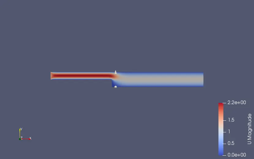
Velocity contour plots
0.2 scaling
0.5 scaling
0.8 scaling
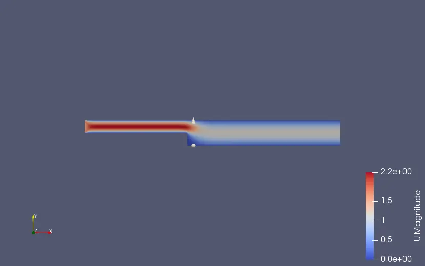
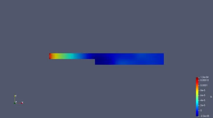
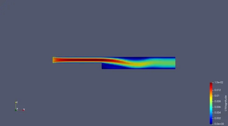
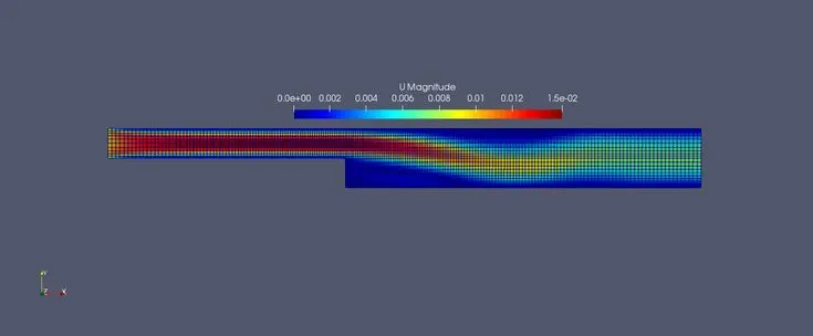
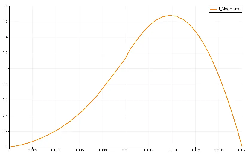
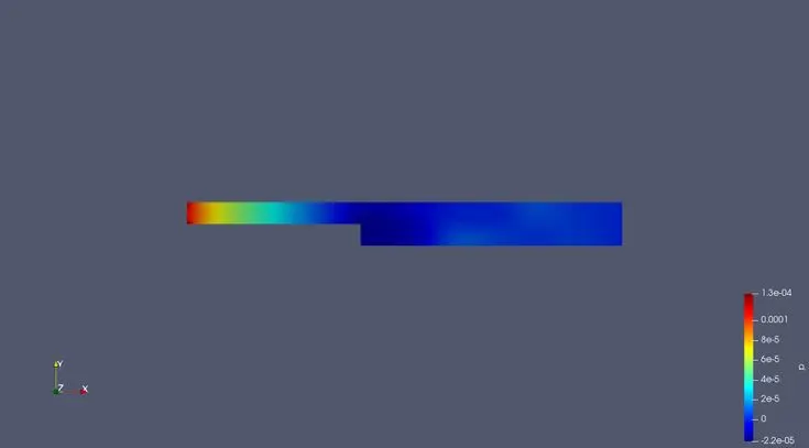
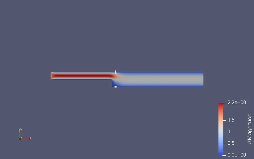
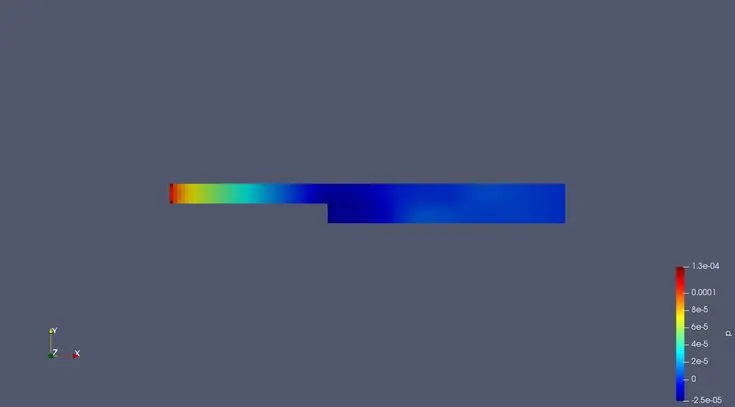
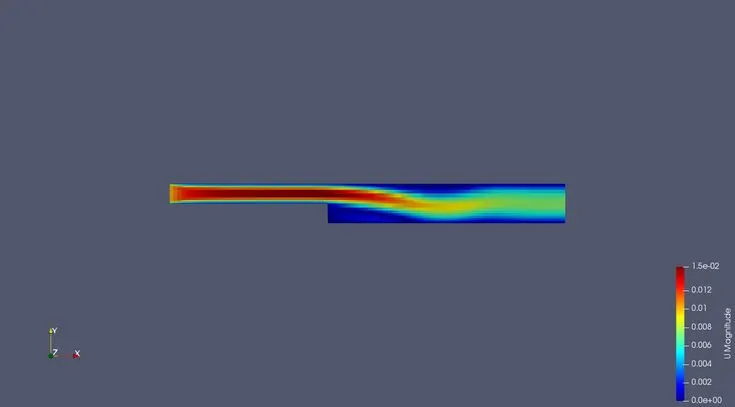
From the above three images, we can see that the mesh grading factor does not affects the visualization of the flow much.There must be some differences but they are not visible from the images.The flow is expected to have loss in pressure and velocity as it goes from the inlet towards the step and to the larger section of the pipe. The drop in pressure creates minor vortices that are smoothened out over time with the flow separating out from the surface of the pipe at the step region and drastically dropping in speed towards the outlet. As the velocity gradient exists at the boundarythe more close grid spacing gives more accurate velocity values.The flow at close proximity of the wall surface affects the flow at the centre of the flow region. the more accurate velocity profile at the boundary leads better results in the flow domain.