Week 7 - Simulating Fluid Sloshing effect inside a Gear-box
Aim: To perform simulation of fluid sloshing effect inside a Gearbox.
INTRODUCTION:
Gearbox:
- A gearbox is a mechanical device used to increase the output torque or change the speed (RPM) of the motor. The motor Shaft is connected to one end of the gearbox. The internal configuration of the gearbox gears provides an output torque and a specific speed determined by the gear ratio.
-
The most basic definition of a gearbox is that it is a mechanical unit or component consisting of a gear train or set of gears embedded in a house, the name itself defines it as a box containing gears. In the most basic sense, a gearbox works like a gear system. Change torque and speed between a drive, such as a motor, and a load.
-
Gears in gearboxes can be one of several types, from bevel and helical gears to worm gears and planetary gears. The gear is mounted on a shaft supported by roller bearings and rotates around it. A gearbox is a mechanical method of transferring energy from one device to another, which is used to increase torque while decreasing speed.
- Gearboxes are used in many applications, including machine tools, industrial equipment, conveyor belts, and almost any power transmission application with a rotary motion that requires a change in torque and speed.
Types of GearThree main types of gearboxes are being used. They are
- Sliding mesh gearbox.
- Constant-mesh gearbox
- Synchromesh gearbox.
PART-1
Geometry:
- The 3D model of the gearbox is imported to Spaceclaim. Extraction of fluid volume is done by volume extraction. Once the extraction of the volume is done, the body is split into toer to extract the 2D geometry in the middle plane. This is done by selecting the fluid domain and copy-pasting it to the new design. Share topology is set to share.
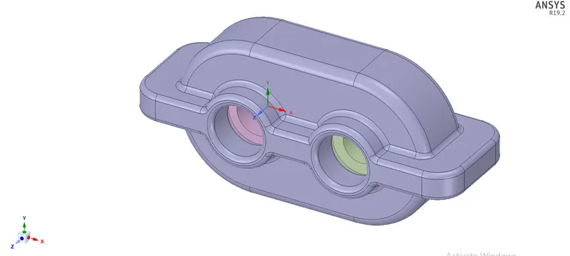
The view of a fluid volume geometry:
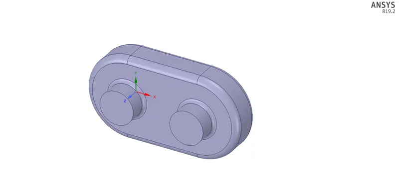
When you click on the plane, choose Split Tool, then click Remove Region, it will appear to be a split body. We need the area that is highlighted, so copy it and paste it into the new design to get the 2D view.
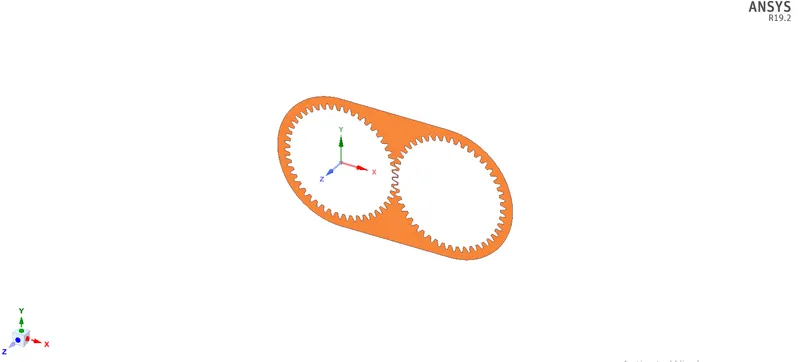
2D view:
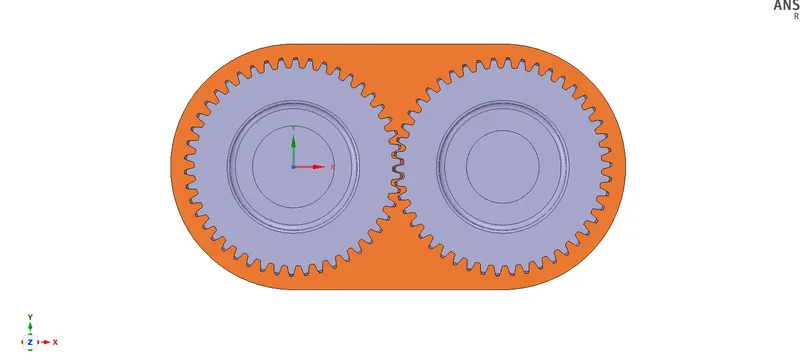
Mesh:
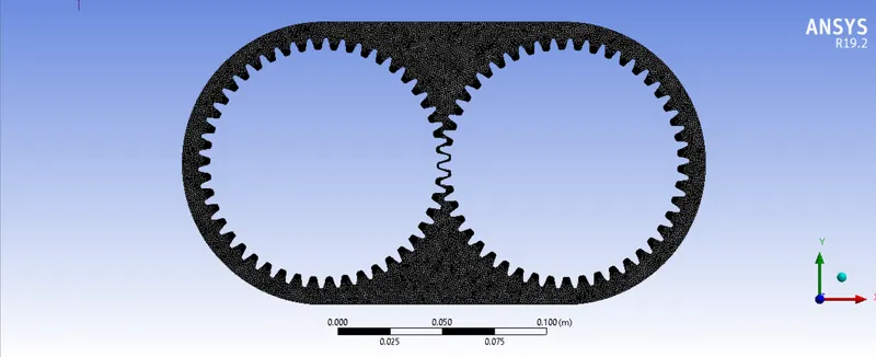
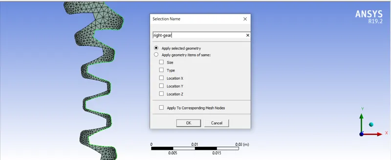
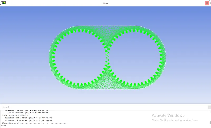
- The triangle meshing method is assigned. The element size of the mesh is 1e-005m. Capture proximity is enabled. The number of cells across the gap is given as 3. The naming of the left and right set of gear teeth is done so that while importing the UDF we can give a left motion to the left set of gears and a right move to the right set of gears.
Total No of Nodes and Elements:

Name Selection:
SETUP:
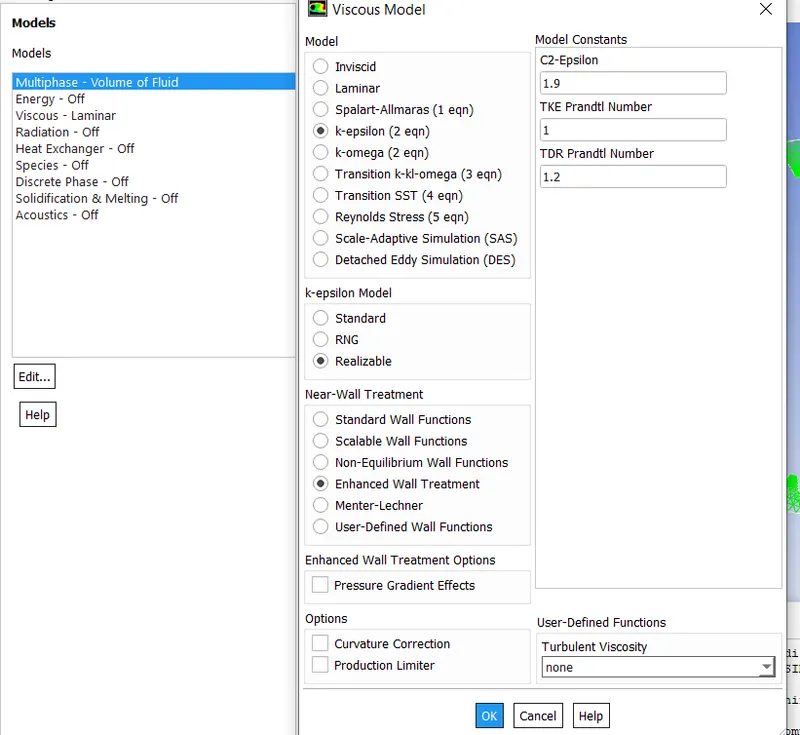
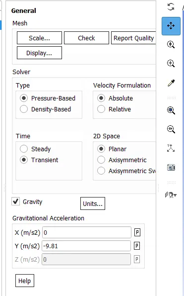
- Multiphase modes < vol of fluids < select implicit < ok, model < k-epsilon < realizable < enhance wall treatment for getting more accurate values < ok < tick on transient time and on gravity < y = -9.81 < ok < for mark and adapt cells we have to calculate the gearbox enclosure and enter the values.
- The total height of the gearbox enclosure: is 135mm.
- 20% of gearbox enclosure: 0.2*135 = 27mm (from bottom)
- 30% of gearbox enclosure: 0.3*135 = 40.5mm (from bottom)
- Dynamic meshing:
- Mesh methods:
- Smoothing: Diffusion
- Remeshing: Local cell
- Minimum length scale: 0.0001
- Maximum length scale: 0.0033
- Maximum cell skewness: 0.5
- Size re-meshing interval: 0
- The motion is assigned using a User-defined function and the centre of gravity location for both the gears was mentioned i.e. (0,0) and (0.115,0).
- Primary phase – air
- Secondary phase – Engine oil or n-heptane-liquid
- Initialization method – Hybrid
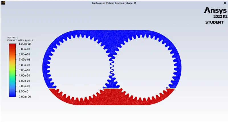
- Mark/Adapt cell: Using the mark option we have to define the fluid region
For 20% immersion:
Xmin = -0.054m Xmax = 0.169m
Ymin = -0.0405m Ymax = -0.0675m
For 30% immersion:
Xmin = -0.06183m Xmax = 0.17683m
Ymin = -0.027m Ymax = -0.0675m
- Once the marking is done, we have to patch it.
- Phase - Engine oil/ n-heptane-liquid
- Variable – volume fraction
- For engine oil/n-heptane-liquid we shall give a value of 1 so that automatically the air will take the value 0.
Contour Setup:
SOLUTION:
PART-1
CASE A- Engine oil:
20% immersion:
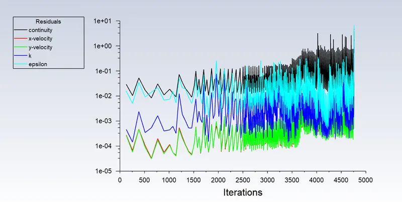
- Residual:
- Volume Fraction:
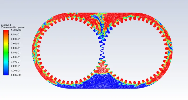
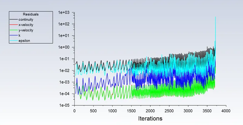
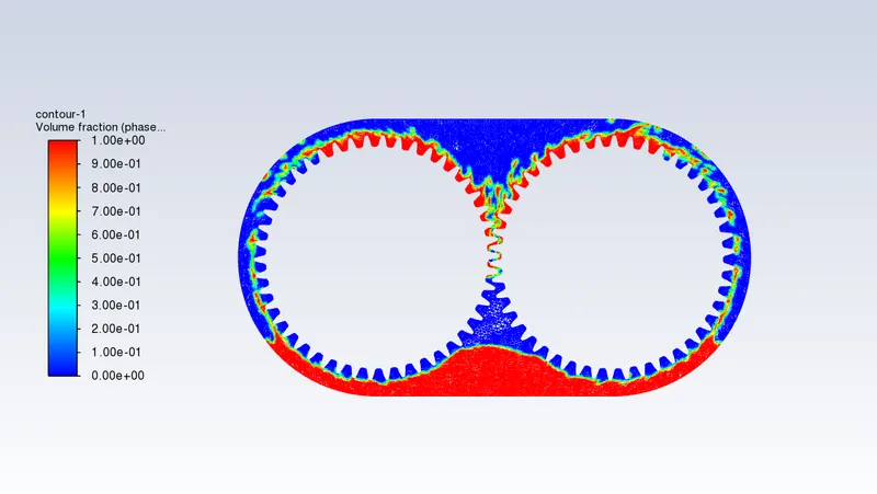
30% immersion:
- Residual:
- Volume Fraction:
CASE B: n-heptane:
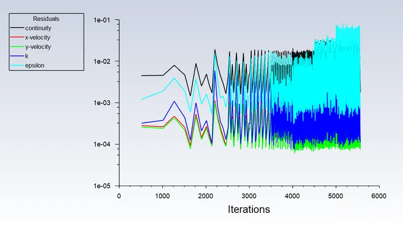
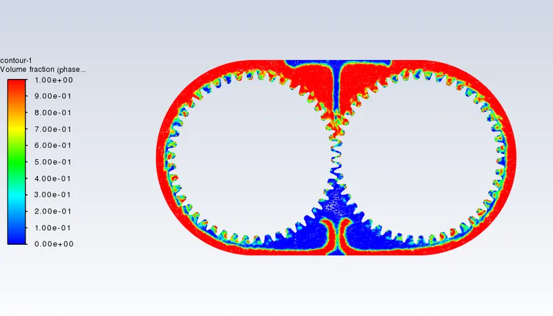
20% immersion:
- Residual:
- Volume Fraction:
30% immersion:
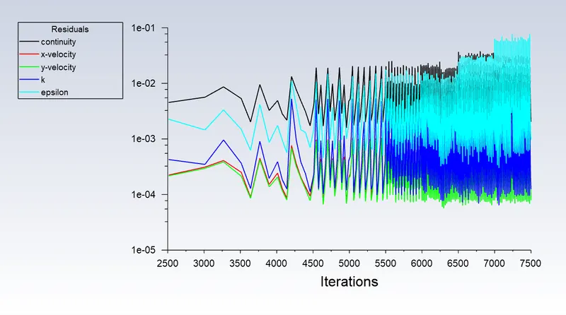
- Residual:
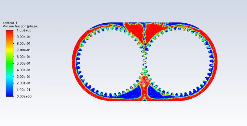
- Volume Fraction:
PART-2:
Sloshing effect:
-
Slosh in fluid dynamics refers to liquid movement inside another object (which is, typically, also undergoing motion). A slosh dynamics problem, where the dynamics of the liquid can interact with the container to significantly change the system dynamics, strictly speaking, requires that the liquid have a free surface.
-
Important examples include the free surface effect (cargo slosh) in ships and trucks transporting liquids, propellant slosh in spacecraft tanks and rockets (especially upper stages), and (for example oil and gasoline). However, the term "fuel slosh" is now frequently used to describe liquid motion in a tank that is full and without a free surface.
-
To describe liquid slosh, numerous mathematical and empirical relationships have been developed. The fluid-structure interaction problem is typically solved using computational fluid dynamics and finite element methods, particularly if the solid container is flexible. The Bond, Weber, and Reynolds numbers are pertinent non-dimensional parameters in fluid dynamics.
-
Slosh is a crucial effect on ships, some aircraft, and spacecraft. Slosh has been linked to numerous spacecraft anomalies, including a near-disaster with the Near-Earth Asteroid Rendezvous satellite, and was a contributing factor in the Falcon 1 second test flight anomaly.
Dynamic meshing:
- A mesh is a network made up of points and cells. It is used to solve partial differential equations and can be almost any size and shape. An individual solution to the equation is represented by one of the mesh's cells. Due to the complexity of the object, it may not be possible to solve the entire object without breaking it up into smaller pieces. Therefore, the mesh is necessary to solve the object.
Types of Meshing:
- Sliding/Moving Mesh: Mesh that Slides or Moves: Using the mesh model, you can create a situation in which various zones move about one another. Rotational or translational motion are both possible. Consider two trains moving through a tunnel as an example.
- Dynamic Mesh: The mesh model enables you to move a cell zone's boundaries about other zone boundaries and adjust the mesh as necessary. In some cases, the boundaries can move rigidly concerning one another, such as when an aircraft wing flap deflects or when pistons move inside an engine cylinder.
- The sliding mesh is a significant subclass of dynamic mesh motion in which the boundaries and cells of a given mesh zone move collectively in a rigid-body motion. The mesh's nodes are moving in space in this case, but the cells they define are not changing shape. Mesh zones that are moving close to one another can also be connected by one or more non-conforming interfaces. The non-conformal interfaces can be dynamically updated as the meshes move and fluid can move from one zone to another as long as the interfaces remain in contact with one another.
The Dynamic mesh model in ANSYS fluent can be used to model flows where the shape of the domain is changing with time due to motion on the domain boundaries. This model can be applied to both single and multiphase flows. And you need to provide a starting volume mesh and a description of the motion of any moving zones in the model.
Three groups of mesh motion methods are available in ANSYS Fluent to update the volume mesh in the deforming regions subject to the motion-defined at the boundaries:
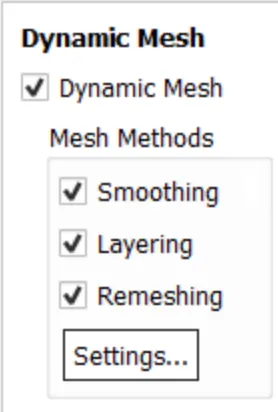
1. Smoothing Methods:
- When smoothing is used to adjust the mesh of a zone with a moving and/or deforming boundary, the interior nodes of the mesh move, but the number of nodes and their connectivity do not change. In this way, the interior nodes "absorb" the movement of the boundary.
Types of Smoothing:
- Spring/Boundary/Laplace layer: For this method, the edges between any two mesh nodes are idealized as a network of interconnected springs. we can use the spring-based method to update any cell or face zone whose boundary is moving.
- Diffusion: This smoothing method is an alternative method to the spring method. It is available for all element types, and you can use it to update any cell zone. It is computationally more expensive than the spring smoothing method, but likely results in better mesh quality.
- Linearly elastic solid: This method supports triangular and quadrilateral elements in 2D and tetrahedral, wedge, hexahedral, and pyramid cells in 3D. It cannot be applied for deforming cell zone containing polyhedral cells. In such cases, the diffusion smoothing method is recommended.
2. Dynamic Layering:
- Even though the cell zone may contain a variety of cell shapes, we can use this method to split or merge cells next to any moving boundary if all of the cells are wedges or hexahedra. Except when the sliding interface is utilised, the one-sided face zones must surround the cell layers.
3. Remeshing Methods:
-
If only mesh smoothing is used, the cell quality may degrade or the cell may become degenerate when the boundary displacement is large relative to the local cell sizes. This renders the mesh useless (for example, results in negative cell volume).
-
To get around this issue, ANSYS Fluent aggregates (collects into a group) cells that don't meet the size or skewness requirements and then locally meshes the agglomerated faces or cells. The mesh is locally updated with the new cells if the new cells or faces meet the skewness criterion. Otherwise, the old cells are kept and the new ones are discarded.
Example of dynamic mesh:
- Gearbox, Flexible artery wall responding to the pressure pulse from the heart, Piston moving inside an engine cylinder.
UDF(user defined function):
-
A UDF is a function that you program that can be dynamically loaded with the ANSYS FLUENT solver to enhance the standard features of the code. These UDFs are written in the c programming language. At the beginning of the UDF file, we can find udf.h(#include "udf. h") of the source code file, which allows definitions for defining macros and other functions to be included during the process.
-
The UDF used in this project is shown below:
#include "udf.h"

DEFINE_CG_MOTION(right_motion, dt, vel, omega, time, dtime)
{
	vel[0] = 0.0;
	vel[1] = 0.0;
	vel[2] = 0.0;

	omega[0] = 0.0;
	omega[1] = 0.0;
	omega[2] = 2.0e2; /* [rad/s]*/
}
DEFINE_CG_MOTION(left_motion, dt, vel, omega, time, dtime)
{
	vel[0] = 0.0;
	vel[1] = 0.0;
	vel[2] = 0.0;

	omega[0] = 0.0;
	omega[1] = 0.0;
	omega[2] = -2.0e2; /* [rad/s]*/
}
- In the above UDF, two functions are defined. The first one belongs to the right gear and the second function belongs to the left gear. Both the gears rotate with a uniform angular velocity of 200 rad/s.
ERRORS:
- 'Dynamic mesh failed' error: This error occurs due to the inappropriate setting of smoothing, meshing, and re-meshing. In the below dynamic mesh figure only smoothing and re-meshing are enabled. Layering was disabled because the geometry was in 2D.
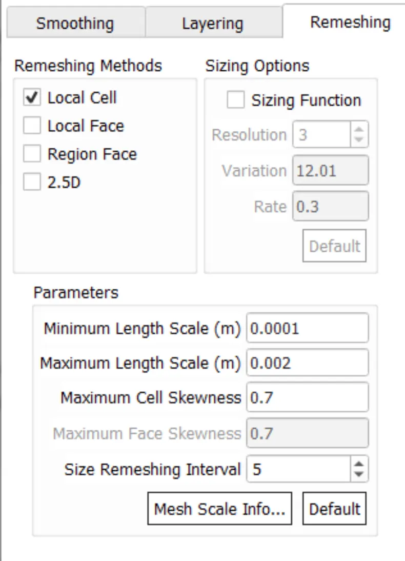
- Negative cell volume detected' error: This error occurs due to the distance moved by a cell per timestep being greater than the cell size in the dynamic region. This error can be resolved by changing the dynamic mesh settings which are shown in the 'Dynamic mesh fail' error.
CONCLUSION:
- Compared to n-heptane, the engine oil has less of a sloshing effect. Less viscosity and greater immersion are what cause the greatest sloshing effect. The viscosity of the engine oil is higher than that of n-heptane. And among all of the previously stated types of situations, the gearbox is best suited to engine oil with a 30% immersion.
REFERENCE: