3D Creation of Celing, Roof, Architectural plan, Structural plan, Sectional view, Elevation view and Camera specific view for a house plan using REVIT
1) Based on the project saved from Week 3, proceed from the First Floor Level. Model a Ceiling from the architecture tab above the walls at the first-floor level
Aim: To Model a ceiling from the architecture tab above the walls at the first-floor level.
Introduction:
- Creating Ceilings in revit is similar as floor creation.
- In the architecture tab the ceiling option is available in that two types are there.
- One is automatic ceiling another is the sketch ceiling.
- When we pick the automatic ceiling means the boundaries of the rooms are automatically get selected.when we place the cursor on that specific room.
- When we choosethe second optin we have to draw the boundaries.
Procedure:
Step-1
- First open the revit software choose week 3 file open it.
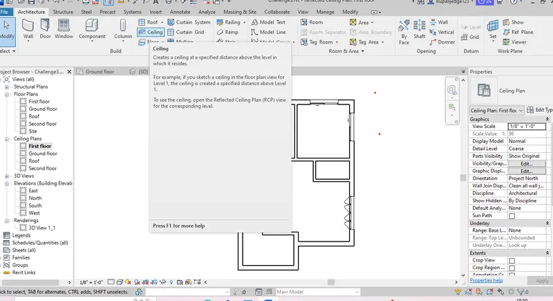
- Go to ceiling plan click on first floor ceiling.
- Go to architecture tab select the ceiling option.
Step2
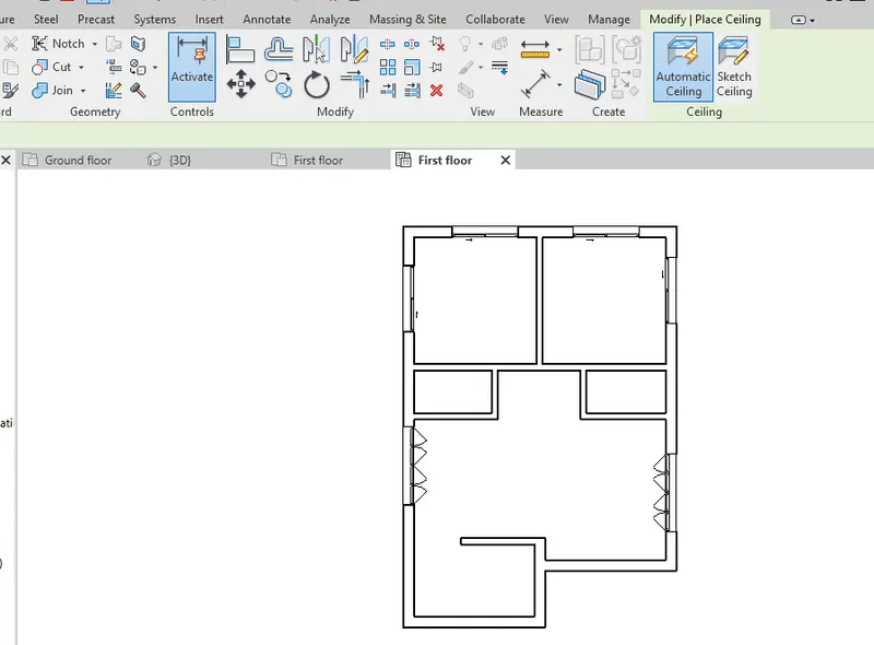
- After selecting the ceiling choose automatic ceiling.
- Place the cursor over each room the boundaries will create.
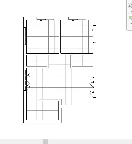
Step3
- Go to 3D view and check the ceilings.
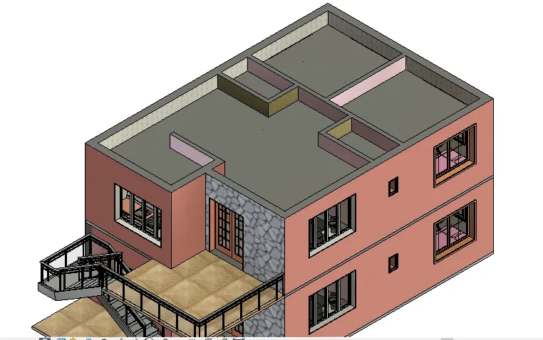
Results:
The ceiling has been created successfully From the arcitecture tab.
2) Model a roof above the ceiling by selecting the footprints of the ceiling. Using the adjustment toolbars appearing on-screen adjust the roof slope to 10 degrees
Aim: To model a roof above the ceiling by selecting the footprints of the ceiling.
Introduction:
- Roof, It is nothing but the topcover of the building, severing to protect against the rain, snow, sunlight wind, and extremes of temperature.
- The different types of roofs are used like flat, pitched, vaulted, domed etc.
Procedure:
Step1:-
- In Floor plan view go to the top level where we have to place the roof.
- After that in ribbon tab select architectural tab in that select the roof drop down it select the roof by foot print.
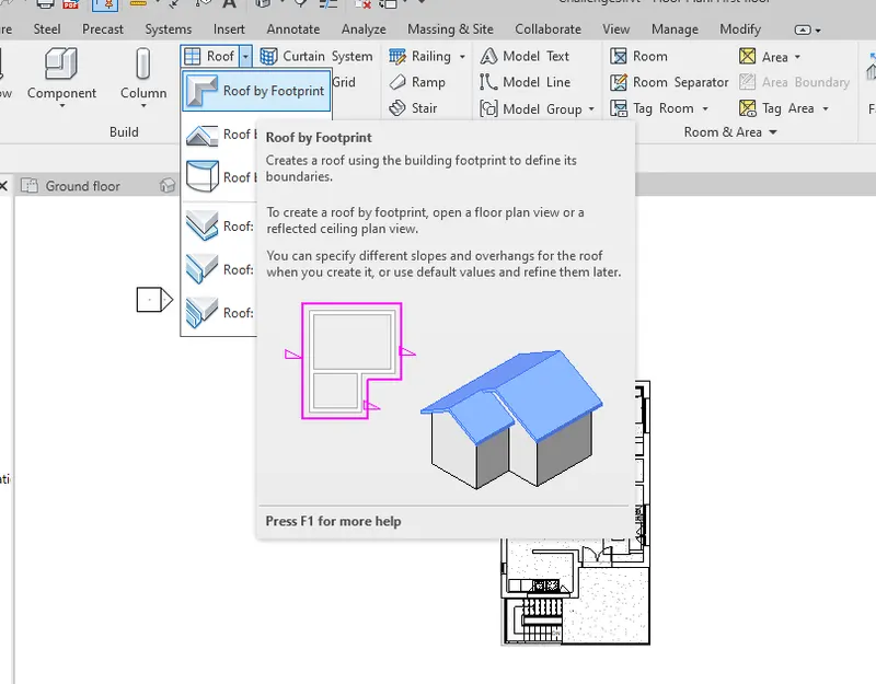
Step2-
- After selecting roof by footprint create the boundaries using line tool.
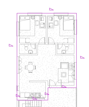
Step3-
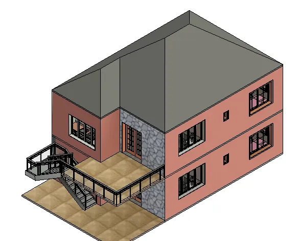
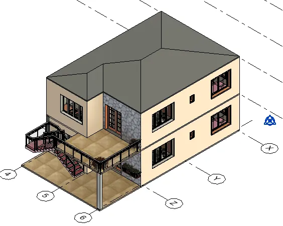
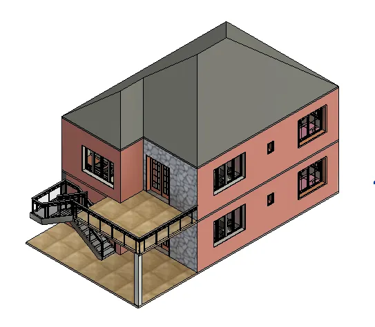
- the roof will created give the slope of roof is 10 degree by changing the units of the slope. by typing on keyboad as UN.
Results:
The roof has been created successfully to the model in the revit.
3) Using the file saved from weeks 2 to 4, create plan views for ground floor level and first-floor level including all the walls, floors, and components. Separate them to
architecture and structural plans
a. Architecture plan must have walls, floors, and all the components placed within the building
b. Structure plan must have details of only walls, floors, and columns
Aim: To create plan views for ground floor first floor level including all the walls, floors, and components. seperate them to architecture and structural plan.
Introduction:
- The structural and architectural plan views are the default views when we open any project templets.
- There is two views one is the floor plan view is nothing but the architectural view.
- Andanother one is the structural plan view.
Procedure:
Step1-
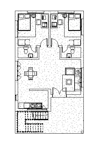
- Go to floor plan view click on ground floor draw the layout which u want using wall tool in the archiectre tab.
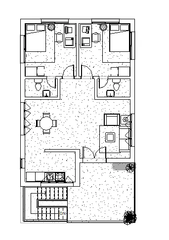
Step2-
- Go to structural plan view there we will get the structuralplan of the building.
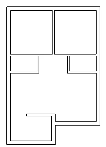
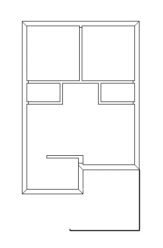
Results:
Created plan views for ground floor level and first flor level including all the walls, floors, and components.
4) Using annotate toolbar add dimensions to all the walls and floors with reference to the longitudinal and transverse grids created in the project file
a. The architecture plan dimensions include details on where the components are placed within the buildings with relation to grids. Overall dimensions are sufficient for architecture plans
b. The Structure plan dimensions must include details on the position of all the walls and interior walls with reference to grids. Locate all the framing components of the building with reference to a fixed point using Structural plans
Aim:
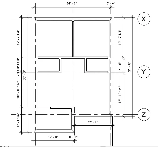
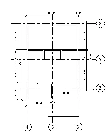
To add dimenssions to all the walls and floors with reference to the to the longitudinal and transverse grids created in the project file.
Introduction:
After creating the layout we must have to provide the dimensions for perticular bedroom, hall, kitchen, dining, restroom etc.
Procedure:
Step1-
- Here we draw the longitudinal and transverse grids to the architectural floor plan. and add the dimensions to that plan from the annotation tab select aligned.
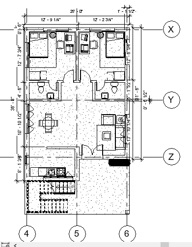
Step2-
- Go to structural plan give the diamensions over there.
Results:
5) Create a sheet template from the view tab and adjust the parameters on the sheet to add appropriate views
Aim: To create a sheet template from the view tab and adjust the parameters on the sheets to add appropriate views.
Introduction:
- Before creating any layout in the revit we to fist add the project information by manage tab.
- After that wehave to give the views. and create the sheets.
Procedure:
Step1-
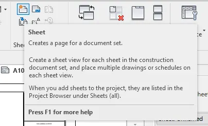
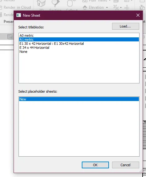
- Select the view tab and and select the sheets load the sheets from table block.
- Choose A1 metric templet the sheet will displayed.
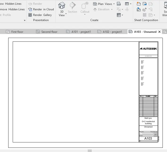
Step2-
- In the sheet template insert architectural plan and structural plan.
- Edit the sheet name and all.
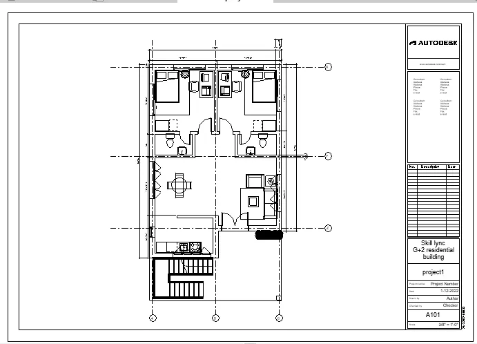
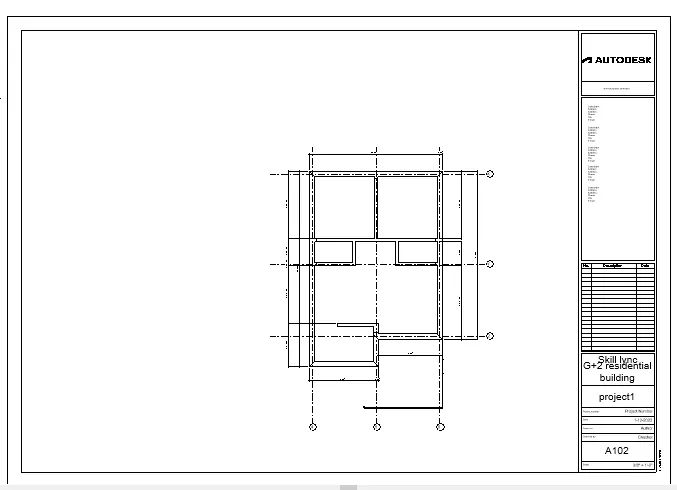
Results:
- Created a sheet template from the view tab and adjusted the parameters on the sheet for adding appropriate views.
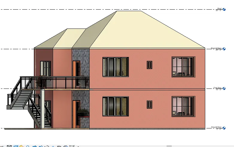
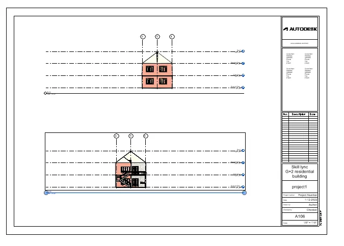
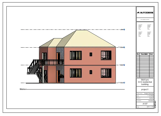
6) Using the elevation tab create the elevation views, looking at your building from East, North, South, and West
Aim:
To Create the elevation views, looking at your building from East, North, South and West using the elevation tab.
Introduction:
- An elevation is a view of a building seen from one side, a flat representation of one view.
- This is the most common view used to describe the external appearance of a building.
Procedure:
Step1-
- First we click on the elevation option from the view toolbar, as shown below.
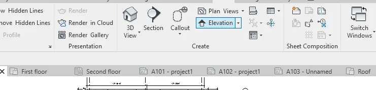
Step2-
- Next the elevation from the east elevation as shown below.
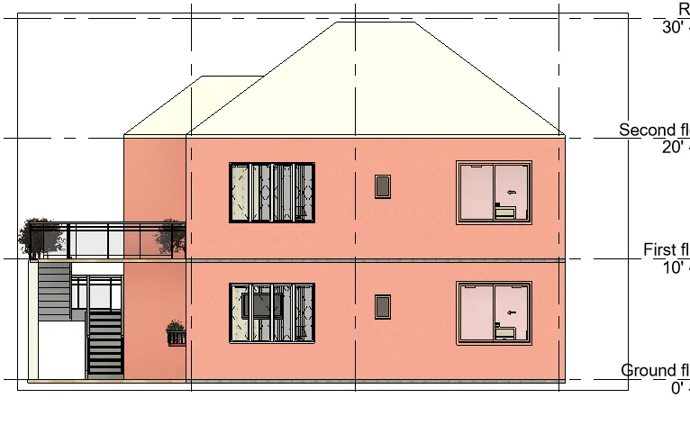 Step3-
- South elevation
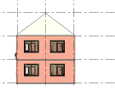
Step4-
- North elevation.
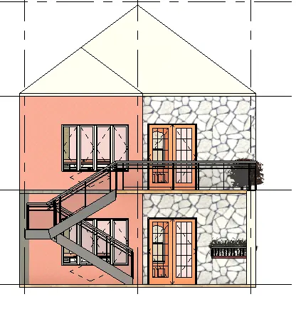
Step5-
- West elevation
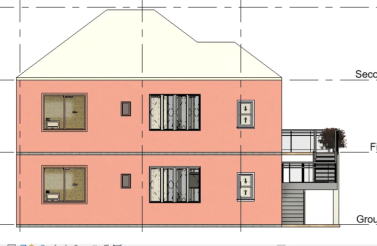
Step 6-
- South east elevation.
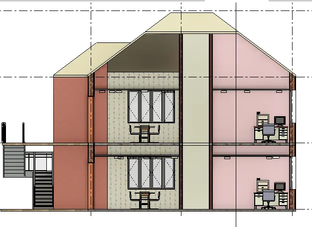
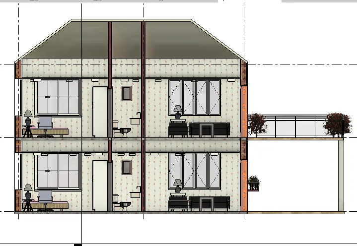
7) Produce section cut through each room either cutting across longitudinally or in a transverse direction
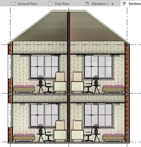
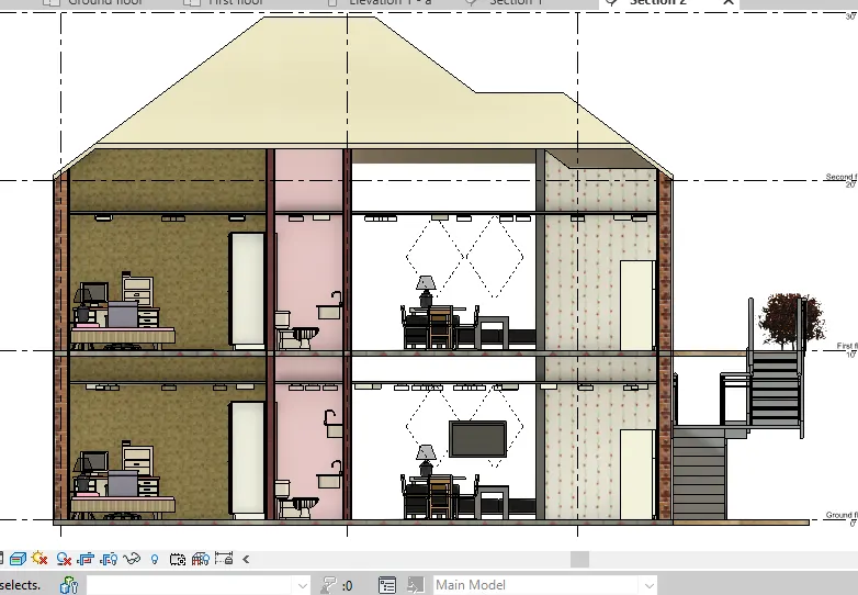
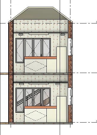
AIM: To produce sectio cut through each room either cutting across longitudinally or in transverse direction.
Introduction:
Sectional views are used in engineering and architecturaldrawings.
Procedure:
Step1-
- First we click on the section from the view tab.
- Next we give the section view.
Step2-
- Section view of toilet. and dining
Step3-
- Section view of kitchen.
Results:
- Created the section views of a model in the revit.
8) Classify the views, Plan Views, Section Views, and Elevation views to either Design or Documentation category using Properties browser
Aim: To classify the views, plan views and elevation views to either design or Documentation catagory using properties browser.
Introduction:
- The structural plan view is the default view when you start a new project using a structural plan view.
- Most projects includes at least one structural plan. New structural plan.
- The floor plan view is the defualt architectural plan.
Pocedure:
Step1-
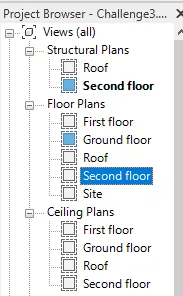
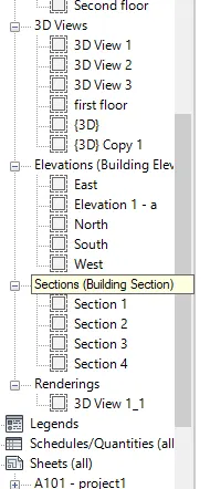
- First we open the project browser, the views are available under the property browser.
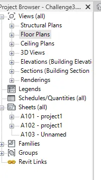
- Below the structural, floor plan, ceiling plan, 3d views these sub elements are present.
9) Using the sheet template produced create multiple sheets as follows
a. A 101- Ground Floor Architecture Plan
b. A 102- First Floor Architecture Plan
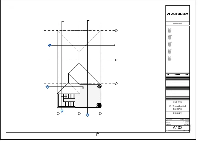
c. A 103- Roof Plan
d. S 101- Ground Floor Structural Plan
e. S 102- First Floor Structural Plan
f. S 103- Roof Framing Plan
g. A-201- North-South Elevations
h. A-202- East-West Elevations
Aim: To create the multiple sheets using sheet templet.
Introduction:
- Before creating any layout in the revit we to fist add the project information by manage tab.
- After that wehave to give the views. and create the sheets.
Procedure:
- Go to ribbon tab select view tab in that select the sheet load the templets.
- Drag the drawing in that sheets.
a. A 101- Ground Floor Architecture Plan
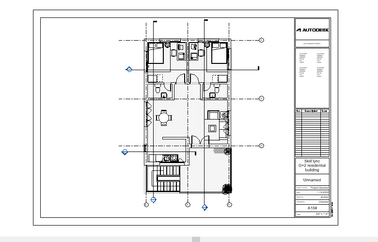
b. A 102- First Floor Architecture Plan
c. A 103- Roof Plan
d. S 101- Ground Floor Structural Plan
e. S 102- First Floor Structural Plan
g. A-201- North-South Elevations
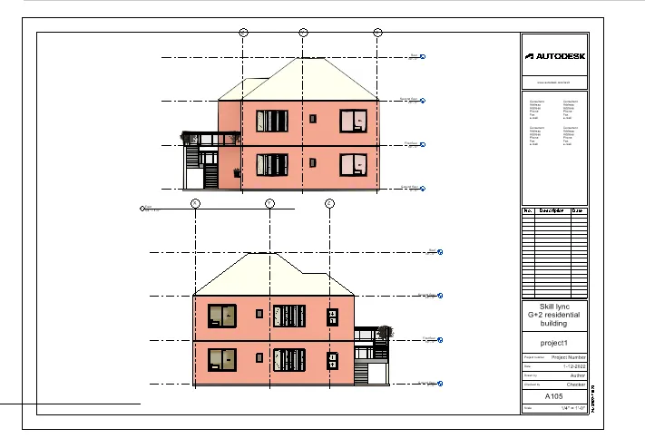
h. A-202- East-West Elevations
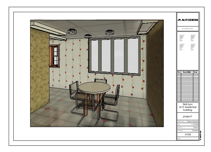
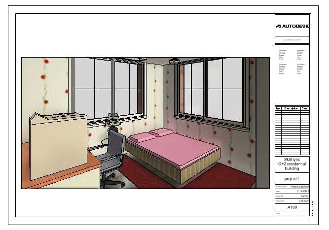
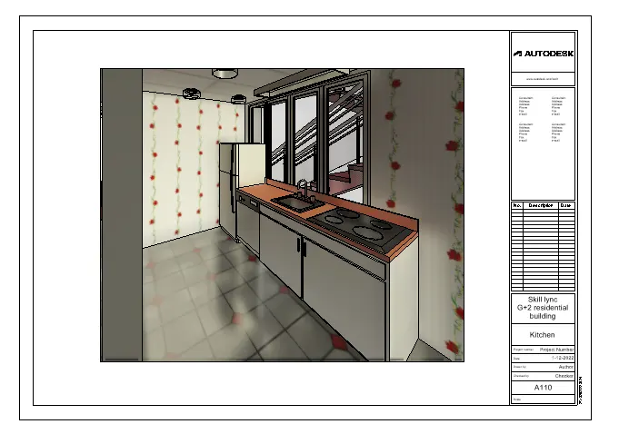
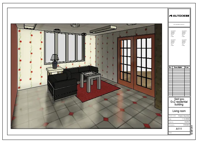
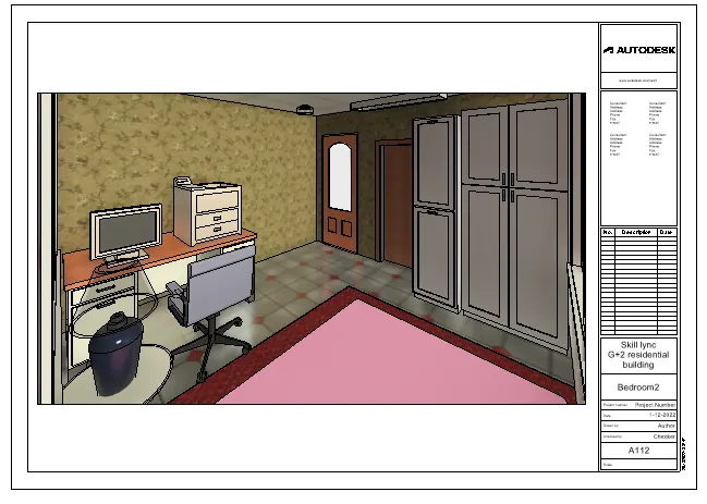
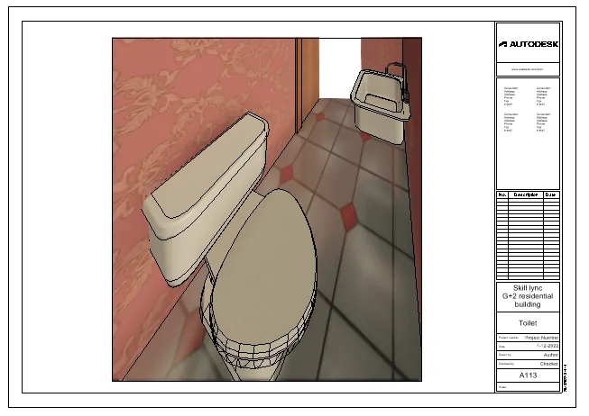
10) Create a camera-specific view or a 3D view in each room ( living, dining, bedroom). Based on the views create a new set of sheets starting A-501 (you can add as many sheets after, 502, 503.. n)to place the 3D view images. Produce the sheets as a part of project drafting.
Aim: To create a camera-specific view or a 3D view in each room.
Procedure: