3D Creation of Celing, Roof, Architectural plan, Structural plan, Sectional view, Elevation view and Camera specific view for a house plan using REVIT
3D Creation of Ceiling, Roof, Architectural plan, Structural plan, Sectional view, Elevation view and Camera specific view for a house plan using REVIT
Introduction
Inorder to create the ceiling and roof for a building using revit software following steps can be followed:
- Ceiling: Open revit software --> Architecture tab --> Ceiling.
- Roof: Open revit software --> Architecture tab --> Roof.
Architecture plan, structural plan, sectional view and elevation view can be developed from the view tab.
- Ribbon --> View --> Plan views: choose any of the plans like floor plan, structural plan etc.
- Sectional view can be developed as follows
- View --> Create panel --> section --> then we have to mark where the section is to be created.
- Elevation : View --> Create panel --> elevation views.
Camera specific view is necessary for rendering a building created which provides a reaistic view for the building. This can be developed from the view tab.
- View --> 3D view dropdown --> Camera. Then place the camera wherever necessary and develop the camera view.
1.
Aim:
To create the ceiling above the walls at the first floor level.
Procedure:
- Initially open the week 3 assignment from the revit software.
- Then, first let us create a verandah in the ground floor as well as first floor level, so that roof can be created for the entire structure.
- For this initially go to plan view.
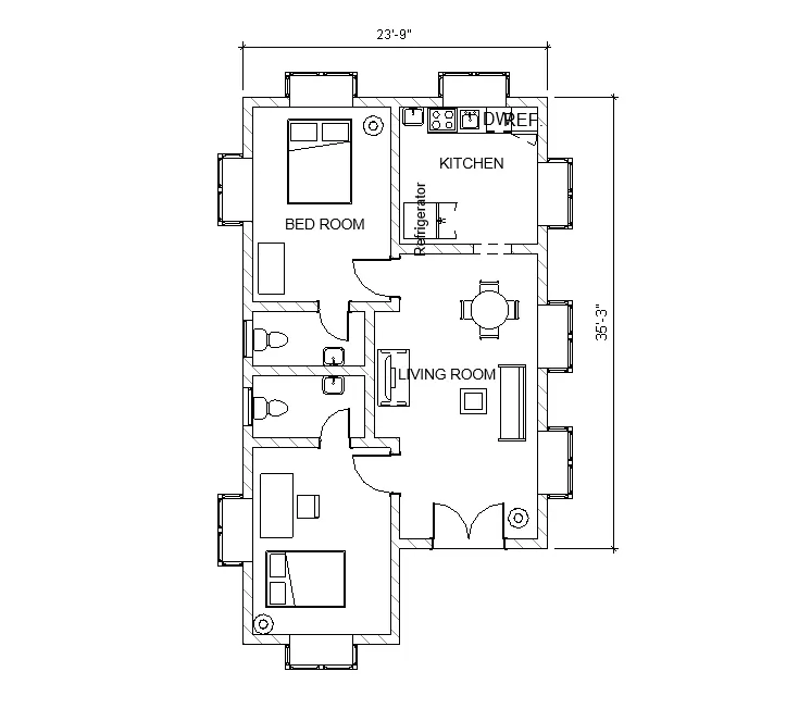
- Then using the floor option create the floor for the verandah portion as given below:
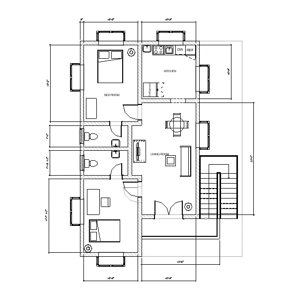
- Next we have to create the railings for the fir floor verandah.
- For this go to railings option in the architecture tab and create the railings.
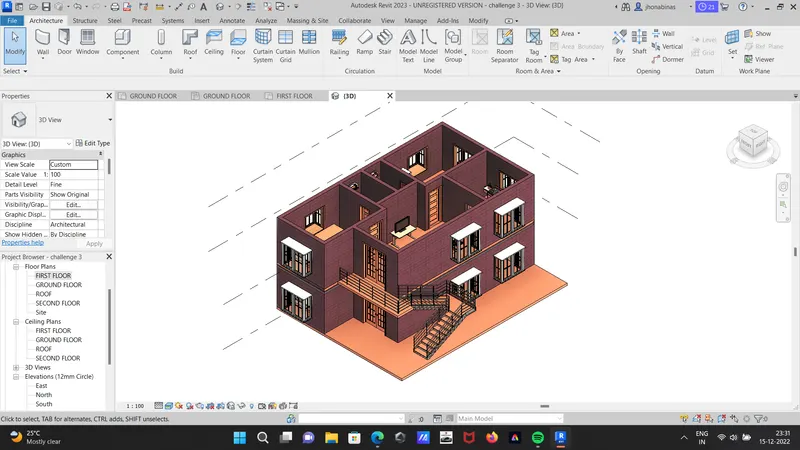
- Now we can place the ceiling, for this go to architecture tab and choose ceiling
 .
. - Ceiling is to be provided in the level 2 for the ground floor.
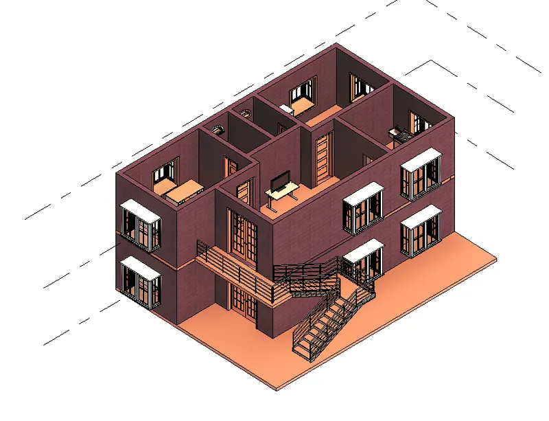
- Hence, the ceiling is created.
2.
Aim:
to model a roof above the ceiling by selecting the footprints of the ceiling and to adjust the roof slope to 10 degrees using adjustment toolbar.
Procedure:
- Inorder to create the roof, initially go to architecture tab of the ribbon.
- Then choose the roof option
 . From the roof dropdown choose roof by footprint.
- Then using the pick wall option in the modify tab create the roof boundary.
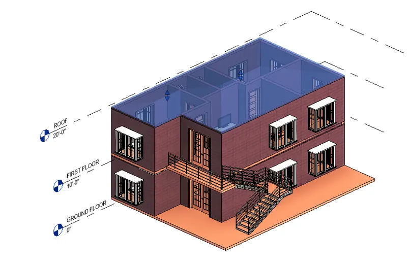
- Now, we have to adjust the roof slope to 10 degrees.
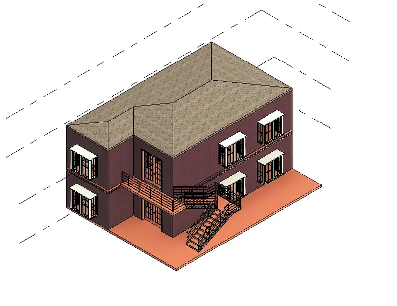
- Hence, 10 degree slope is created.
3.
Aim:
To create plan views for ground floor level and first-floor level including all the walls, floors, and components and then separate them to
a) Architecture plan
b) Structural plans.
Procedure:
a) To create architecture plan:
- Initially go to view tab of the ribbon then select plan views.
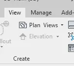
- In the plan views, select floor plan.
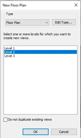
- Click level 1 and go to edit type.
- Choose view template applied to new views.
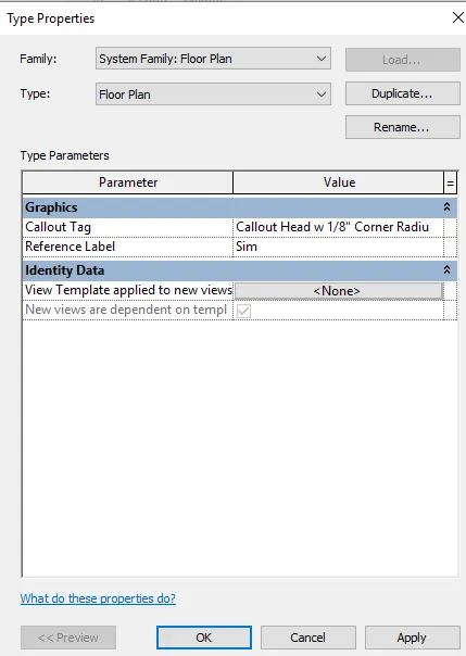
- In that select architectural plan.
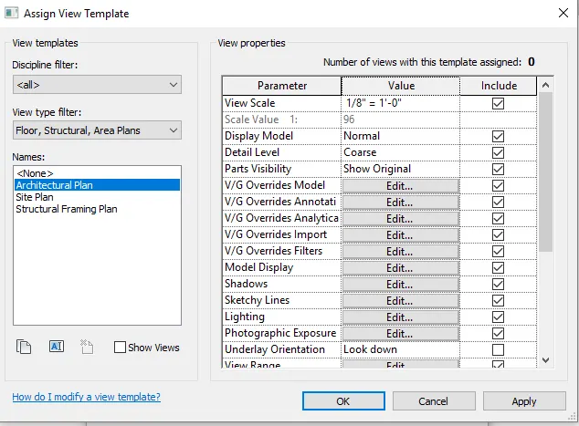
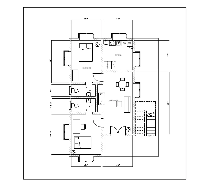
- Then the floor plan is obtained as follows:
- Ground floor plan:
- First floor plan:
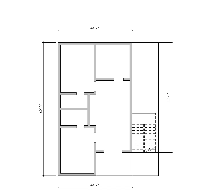
b) To create the structural plan: For this the plan will contain only walls floors and the column as the structural element and is given as follows:
- Ground floor structural plan:
- First floor structural plan:
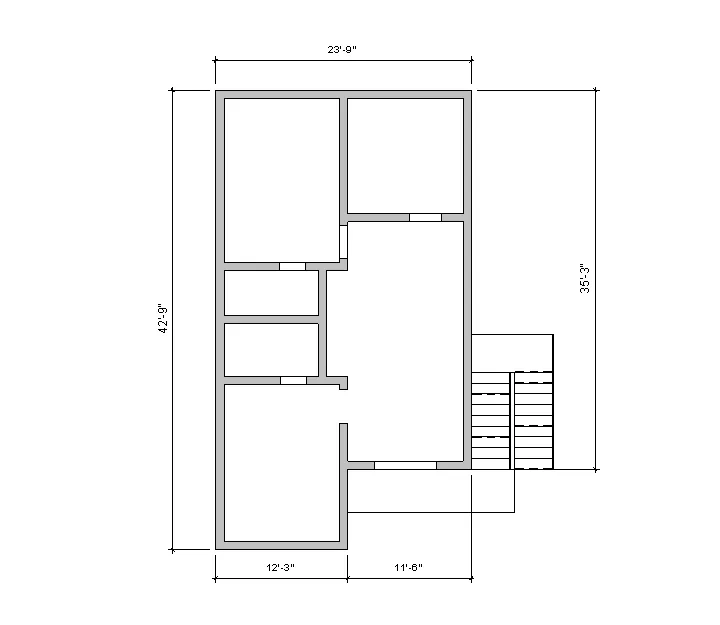
- Hence, structural plan is also developed.
4.
Aim:
To add dimensions to all the walls and floors with reference to the longitudinal and transverse grids created in the project file.
a. The architecture plan dimensions include details on where the components are placed within the buildings with relation to grids.
b. The Structure plan dimensions must include details on the position of all the walls and interior walls with reference to grids.
Procedure:
a)
- Initially select the floor plan for ground floor.
- Go to annotate tab and choose linear dimension and provide linear dimensions in the plan.
- For ground floor:
- For first floor:
b)
- Now we have to create the structural plan dimensions acoording to grid lines.
- For this, go to structural plan.
- Then go to architectural tab, select grids and draw grids along the walls.
- Ground floor:
- First floor:
5.
Aim:
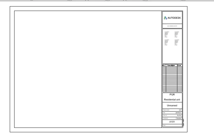
To create a sheet template from the view tab and adjust the parameters on the sheet to add appropriate views.
Procedure:
- Initially go to view tab of the panel.
- Choose sheet option in the sheet composition panel of the view tab.
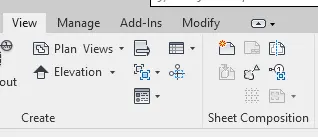
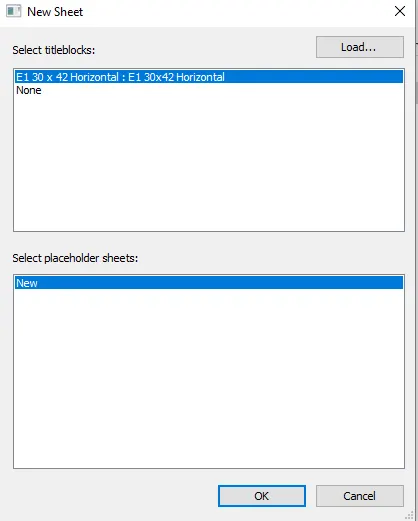
- Click load option and load more templates.
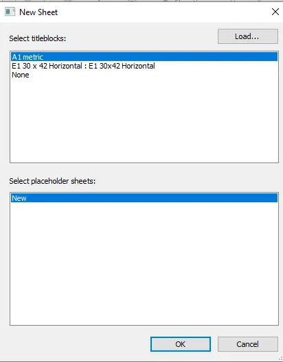
- Select the template and click ok.
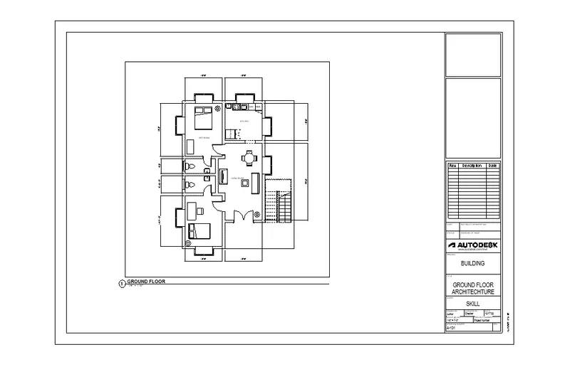
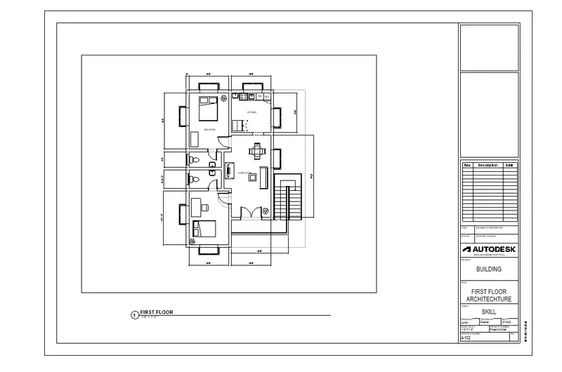
- Now, choose the view that is to be added in the template.
- Add view to the sheet and then adjust the scale so that it fit to the template.
6.
Aim:
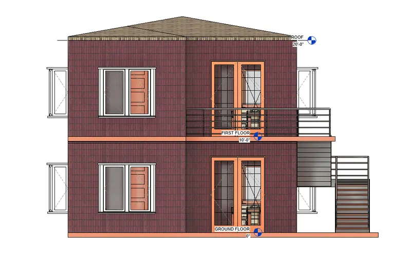
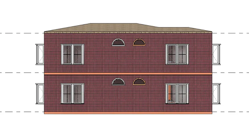
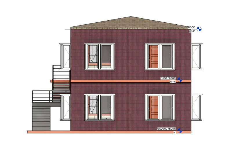
To create the elevation views, looking at your building from East, North, South, and West.
Procedure:
- Initially go to view tab of the ribbon.
- Choose elevation view.
- Then create the elevation view --> north, south, east and west.
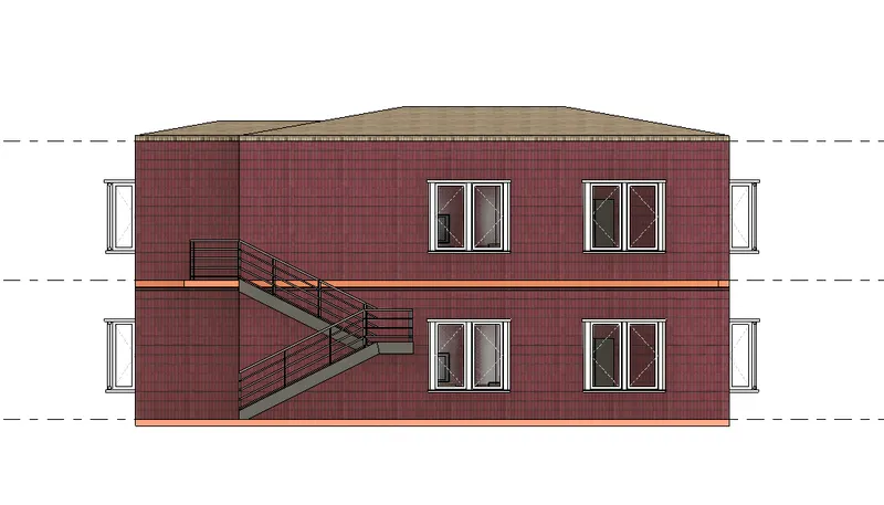
- The elevation views thus obtained are:
- East:
- South:
- West:
- North:
7.
Aim:
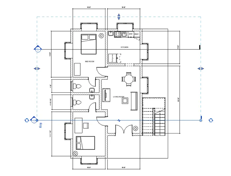
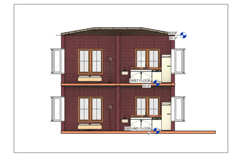
To produce section cut through each room.
Procedure:
- Go to view tab of the ribbon.
- Select the section view and then section the required room.
- Section 1 & 2:
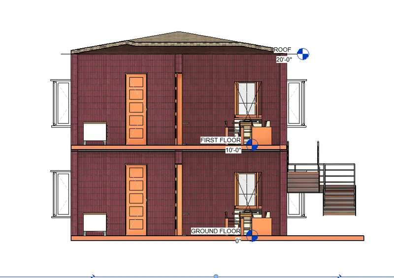
- Section 3 & 4:
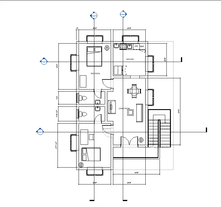
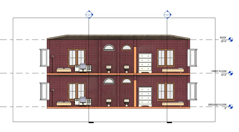
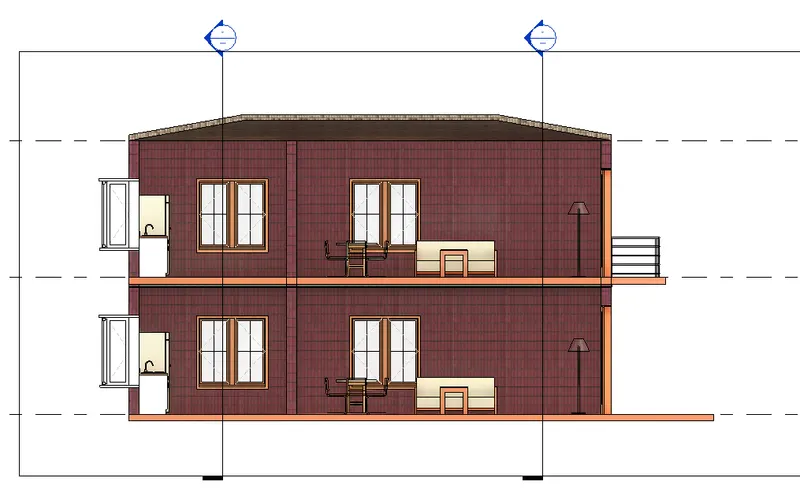
- Hence, four sections have been created.
8.
Aim:
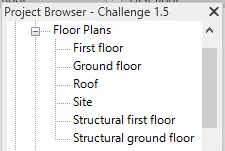
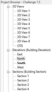
To classify the views, Plan Views, Section Views, and Elevation views to either Design or Documentation category using properties browser.
Procedure:
- Go to view tab of the ribbon.
- Choose property browser.
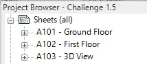
- The following are the different views created.
9.
Aim:
To create sheet template and add different views in it.
Procedure:
- Go to view tab of the ribbon panel.
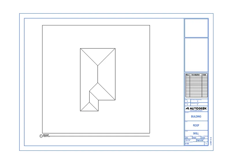
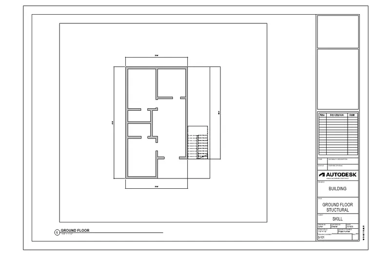
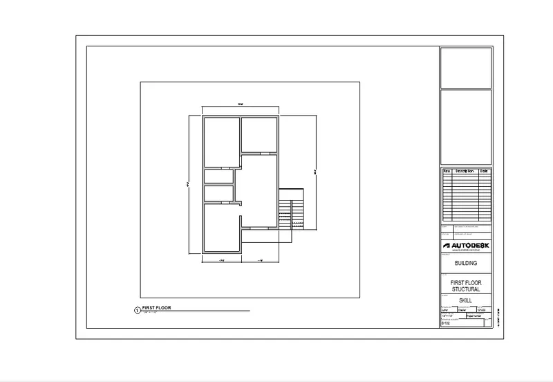
- Choose sheet option and load the template required.
- Then add the views in it.
a) Ground floor Architectural plan.
b) First floor Architectural plan.
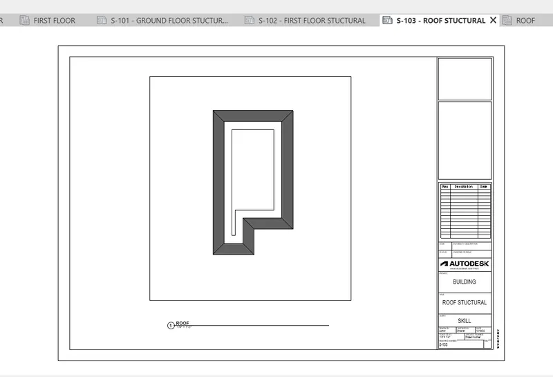
c) Roof plan.
d) Ground floor structural plan.
e) First floor structural plan.
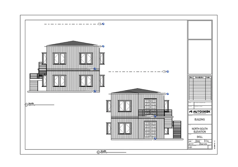
g)North-south elevation
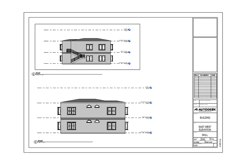
h) East-West elevation
10.
Aim:
To create a camera-specific view or a 3D view in each room.
Procedure:
- Inorder to create a camera specific view, first go to view tab.
- Then choose 3D drop down and in that choose camera.
- Now place the camera in the plan view at suitable location to obtain the camera view.
- Different camera views are then produced in a template.
- Ground floor(GF) views are as given below:
1. Living space- GF
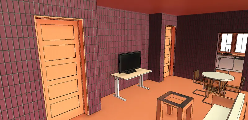
2. Dining space- GF
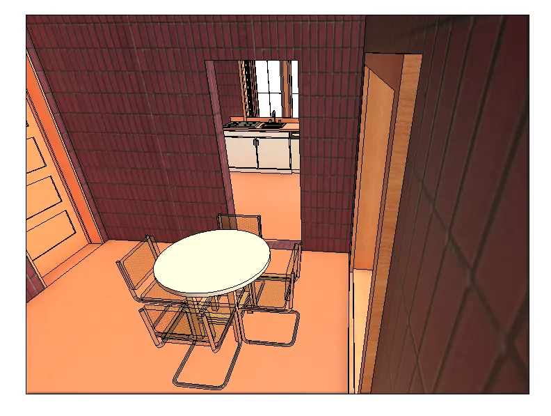
3. Kitchen-GF
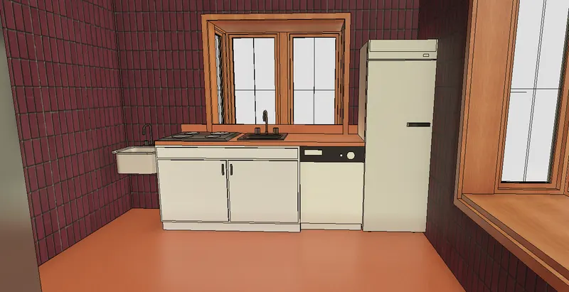
4. Bedroom(view1)-GF
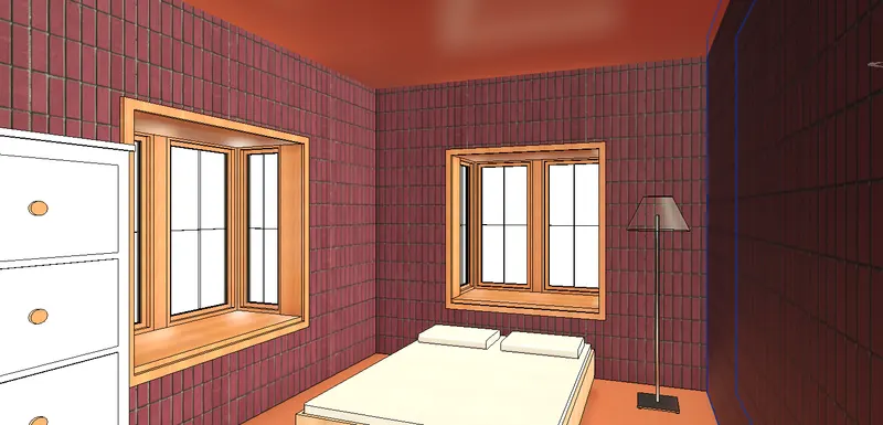
5. Bedroom(view2)-GF
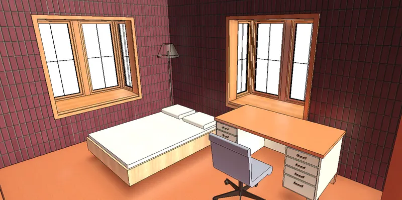
6. Toilet-GF
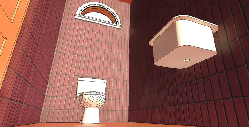
All the bedroom and toilet views are identical.
- Now, we have to create a new set of sheets starting from A501, A502 ....
- View-->sheets-->select the template for the sheet.
- Then we have to include these views to these sheets.
- View-->place a view.
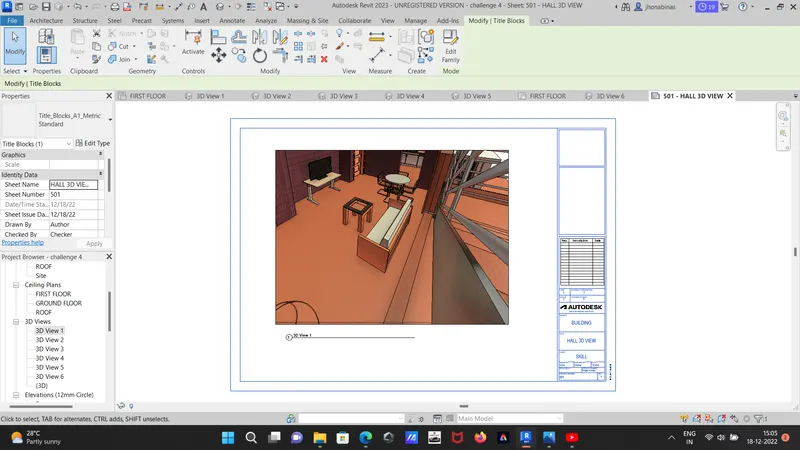
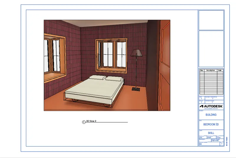
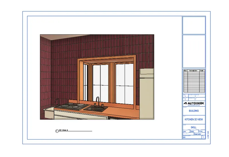
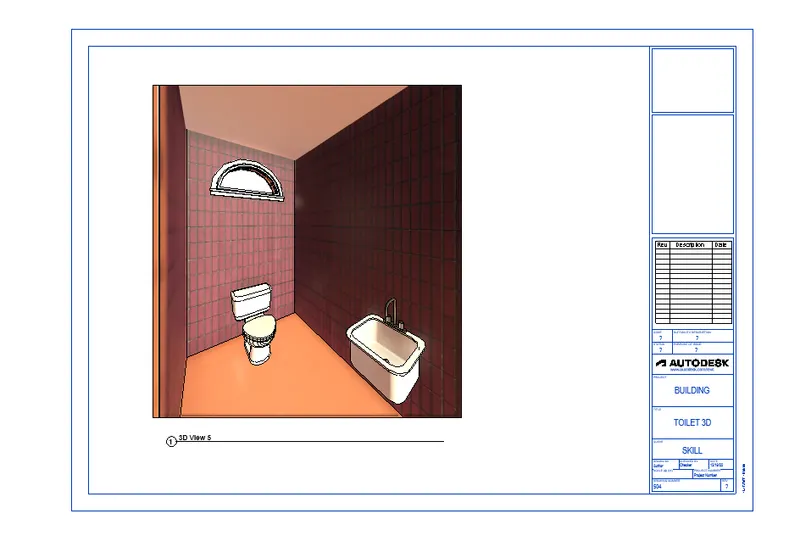
- Hence, all the views are added to the sheets.