3D Creation of Celing, Roof, Architectural plan, Structural plan, Sectional view, Elevation view and Camera specific view for a house plan using REVIT
AIM :- Model a ceiling from the architectural tab above the walls at the first-floor level.
INTRODUCTION :- A ceiling is an overhead interior surface that covers the upper limits of a room. It is not generally considered a structural element but a finished surface concealing the underside of the roof structure or the floor of a story above.
PROCEDURE :-
- Open Revit software
- In home page select the last week saved project
Creating ceiling
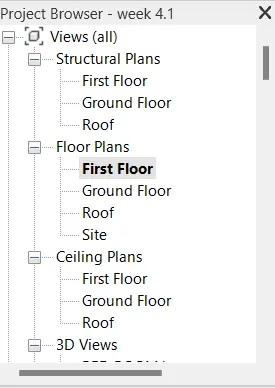
- Open first floor flan from project browser
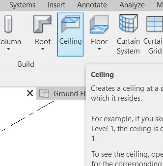
- Go to architectural tab
- Click on ceiling tab
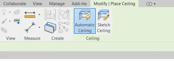
- Now at modify/ceiling space select sketch ceiling
- Then at modify/create ceiling boundary select pick line
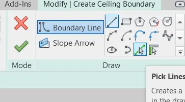
- Then select the outer 4 line of layout
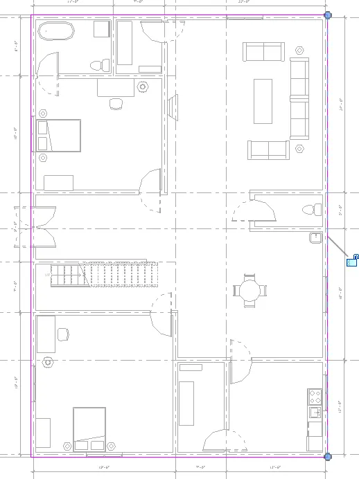
- Then tick the green right mark then enter
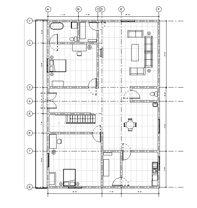
RESULT :- Ceiling of the layout is created successfully according to the layout by following all the process what it required to create ceiling. The height offset of the ceiling is changed from the properties of the ceiling. Type is selected as 2’x4’ ACT system. The result after placing the ceiling over the first floor is shown.
AIM :- Model a roof above the ceiling by selecting the footprints of the ceiling.
INTRODUCTION :- A roof is a top covering of a building, including all materials and constructions necessary to support it on the walls of the building or uprights, protecting against rain, snow, sunlight, extremes of temperature and wind. A roof is part of the building envelope.
PROCEDURE :-
- From the last start for 2nd question
Creating roof above the ceiling
- Open first floor flan from project browser
- Go to architectural tab
- Click on roof tab
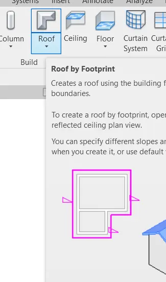
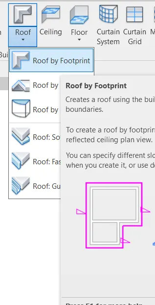
- Then select roof by footprint
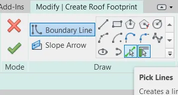
- Then at modify/create ceiling boundary select pick line
- Then select the outer 4 line of layout
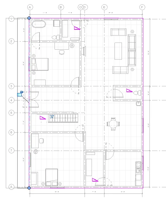
- Then tick the green right mark then enter
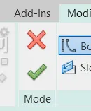
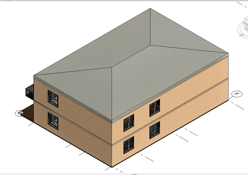
- Now go to 3D view of plan
- Then select the roof then type UN command
- Then change the slop at 10 degree cause it mentioned in question
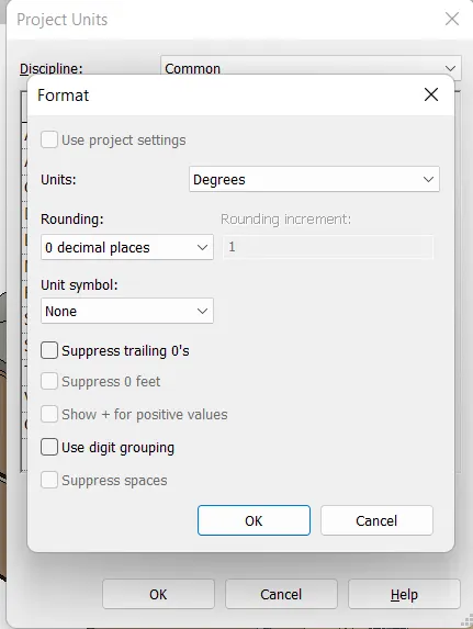
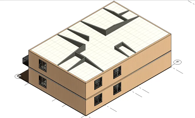
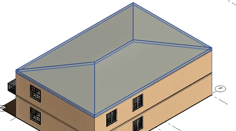
RESULT :- The roof is created above of the ceiling by selecting the footprint of the roof.
Roof of the plan type is basic roof generirc-9”.
AIM :- Create plan view for ground floor level & first-floor level & separate them into Architectural and structural plans.
INTRODUCTION :- In the field of architectural, an architectural plan is design and planning for a building and can contain architectural drawings, specifications of the design, calculations, time planning of the building process and other documentation.
A structural drawing, a type of engineering drawing is a plan or set of plans and details for how a building or other structure will be built. Structural drawings are generally prepared by registered professional engineers and based on information provided by architectural drawings.
PROCEDURE :-
- From the last start for 3rd question
- Architectural plan
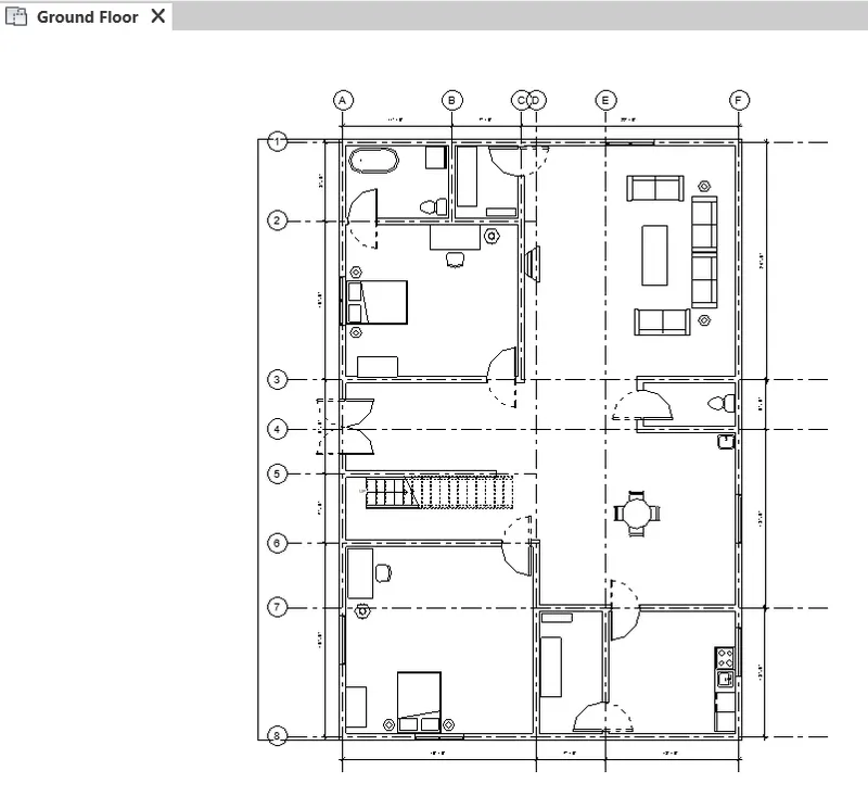
Ground floor
- Now go to view tab on ribbon
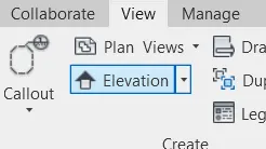
- Now click at plan view
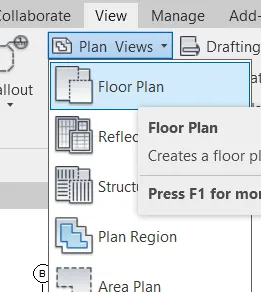
- Now click at floor plan
- Now edit type then select the architectural template
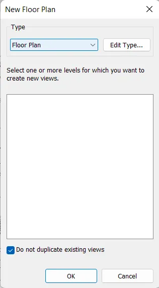
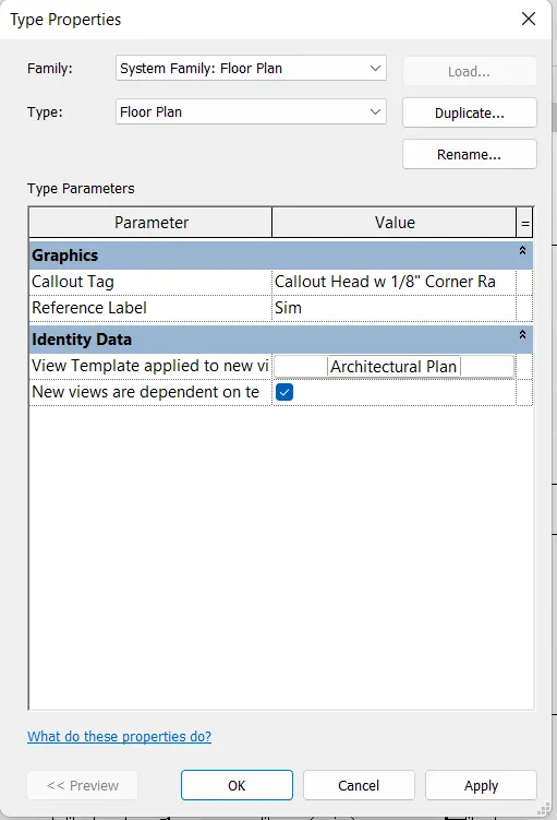
- Then apply then okay
First floor
- Do the same thing for first floor plan
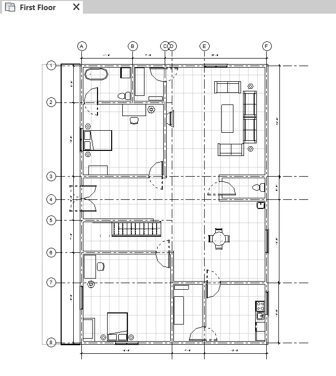
- Structural plan
Ground floor
- Now go to view tab on ribbon
- Now click at plan view
- Now click at structural plan
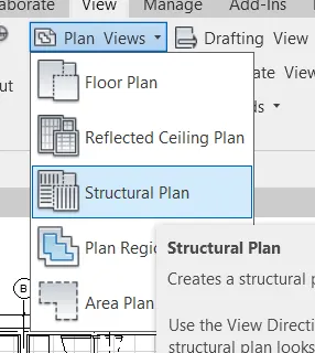
- Now edit type then select the architectural template
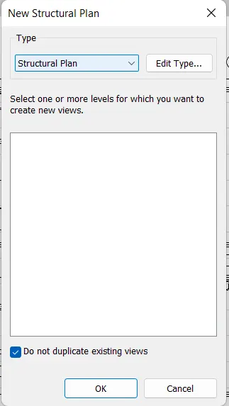
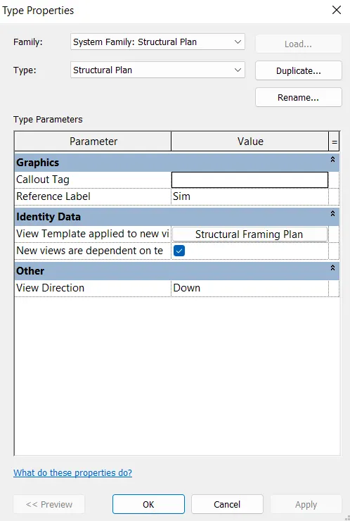
- Then apply then okay
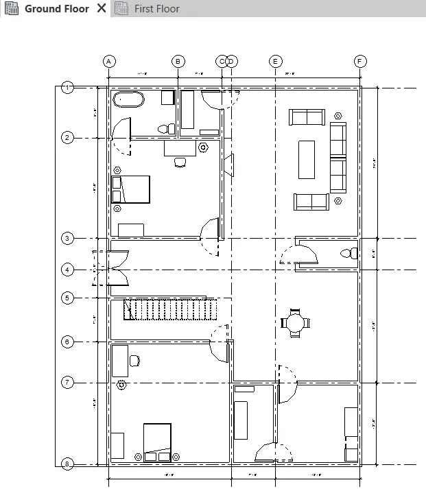
First floor
- Do the same thing for first floor plan
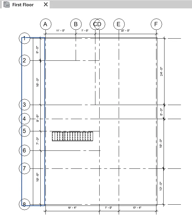
RESULT :- Created the plan view for ground floor level &first-floor level separately for Architectural plan & structural plan. Procedure is shown in detailed in procedure section.
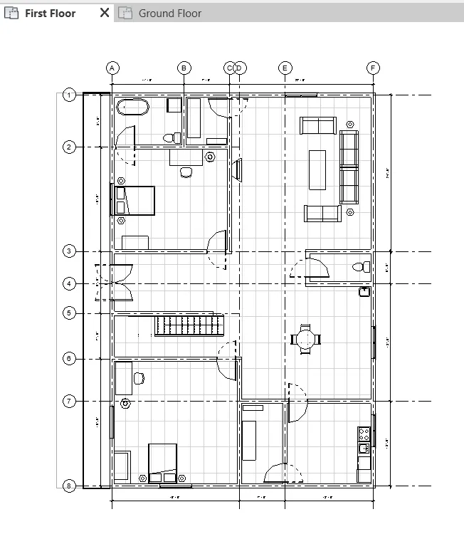
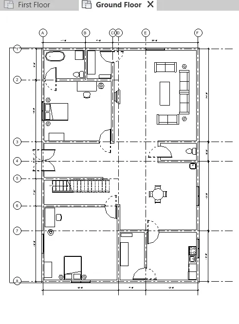
AIM :- Annotate the project concerning the longitudinal and transverse grids created in the project files.
INTRODUCTION :- Annotation tool bar is used to show the dimensions along the grids to the longitudinally & transversally In to the projects.
PROCEDURE :-
Creating grids
- Go to the architectural tab
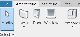
- Now at the right side there is Grid option select that
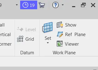
- Now create grids between the walls horizontally & vertically respectively
- Adjust the length of grids as required
- Rename the required grids respectively
- Horizontal grids are named as 1 to 8
- Vertically grids are named as A to F
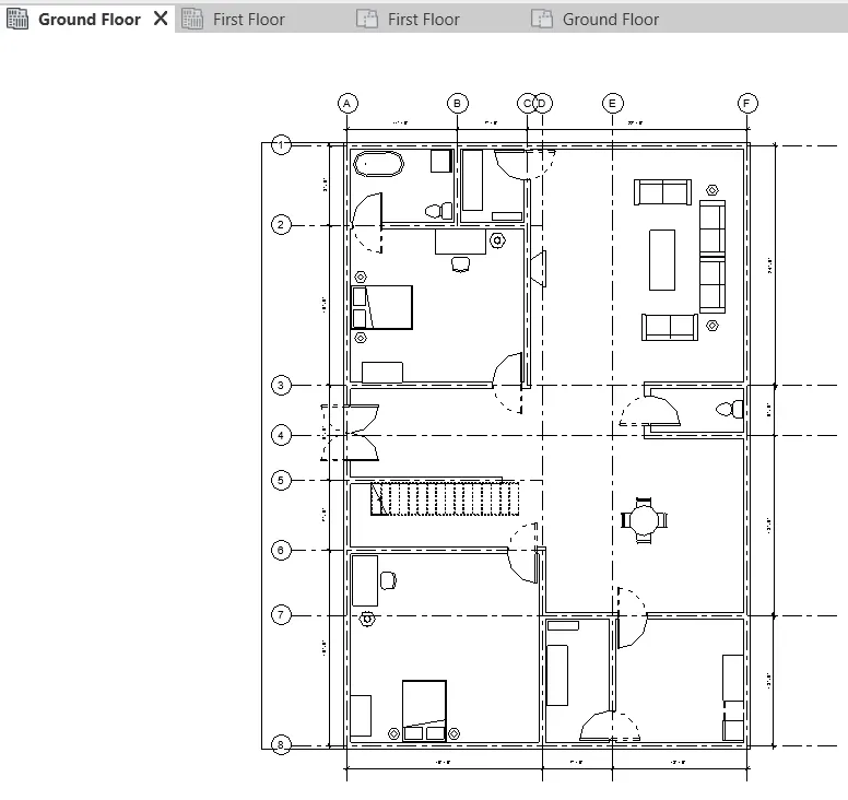
- Architectural annotation
- Select the ground floor from project browser & first floor respectively
- Now select the annotate tab at ribbon
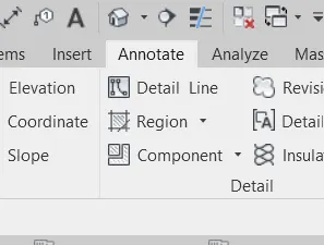
- Then select the linear option
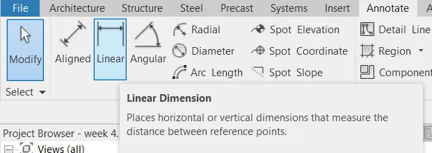
- Select grids line 1st & 2nd at where you want to show dimensions
- Do the same thing for showing all dimensions
- Structural annotation
- Select the ground floor from project browser & first floor respectively
- Now select the annotate tab at ribbon
- Then select the linear option
- Select grids line 1st & 2nd at where you want to show dimensions
- Do the same thing for showing all dimensions
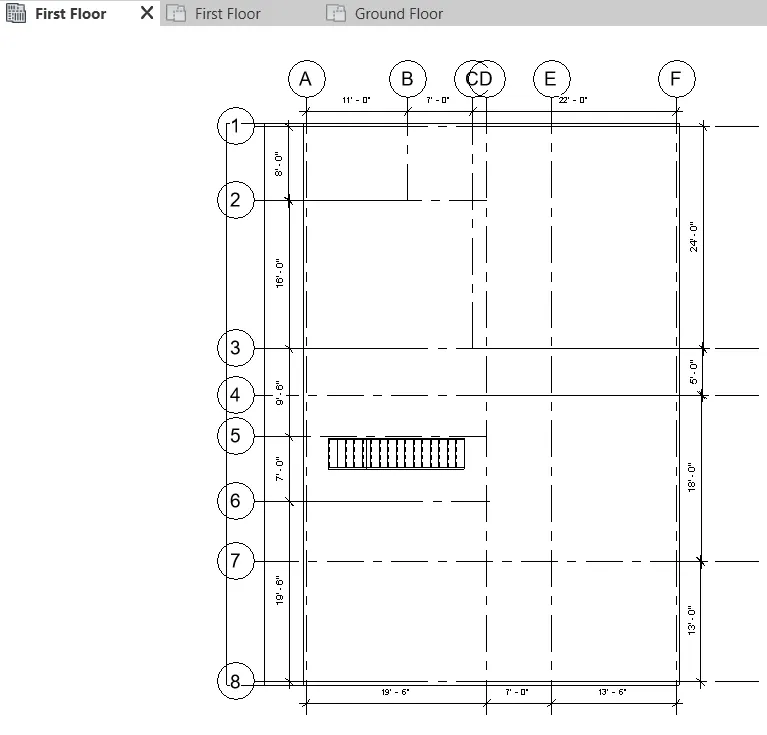
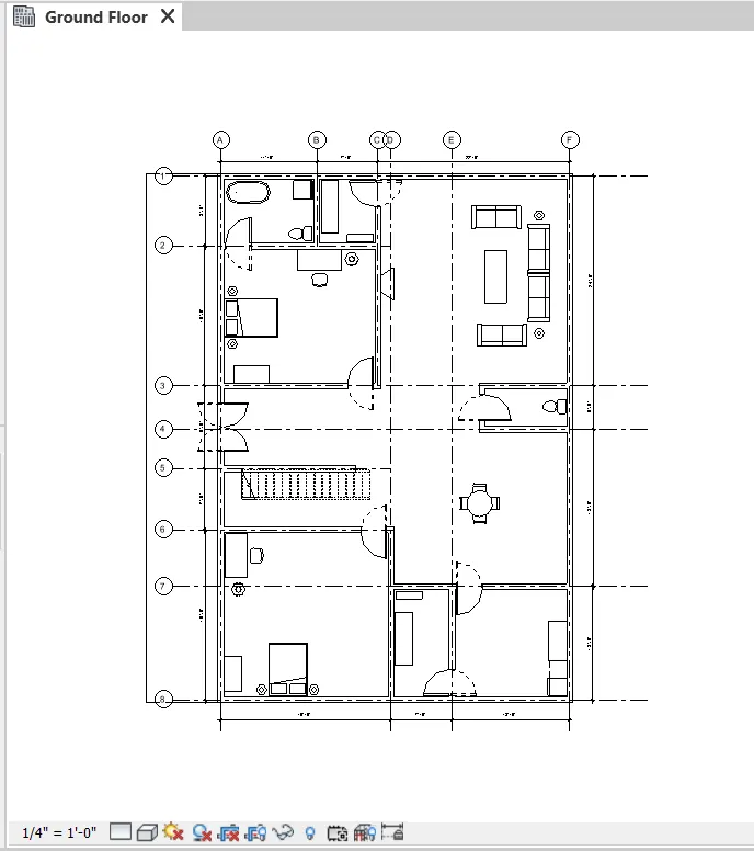
RESULT :- By the use of annotate tab the dimensions are shown above at the both section a & b. respectively all the procedure are shown above briefly.
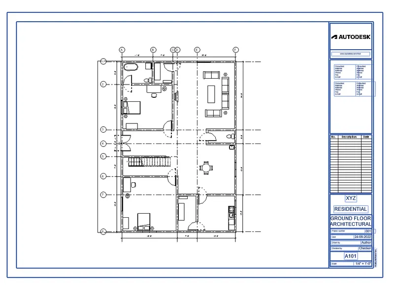
AIM :- Create a sheet template from the view tab and adjust the parameters on the sheet to add appropriate views.
INTRODUCTION :- In Revit, you create a sheet view for each sheet in the construction document set. You can place multiple drawings or schedules on each sheet view. About sheets in project templates. Create views on project template before you start building the model to streamline the project documentation process.
PROCEDURE :-
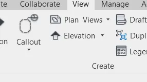
- Go to the view tab at ribbon
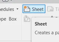
- Now select the sheet option there
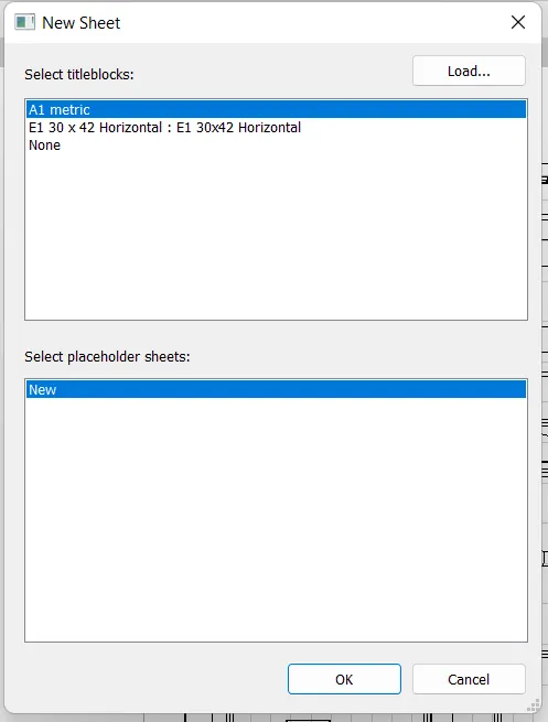
- Then this dialog box will appear there chose page then okay
- Then fill all the things what that sheet requires
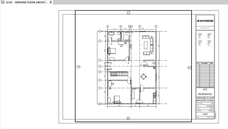
- Then from the project browser select the ground floor and drag it to the sheets
- Then place at center then set the scale for the fit of sheet
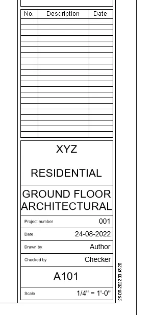
RESULT :- Created a sheet template from the view tab and adjusted the parameters on the sheets accordingly.
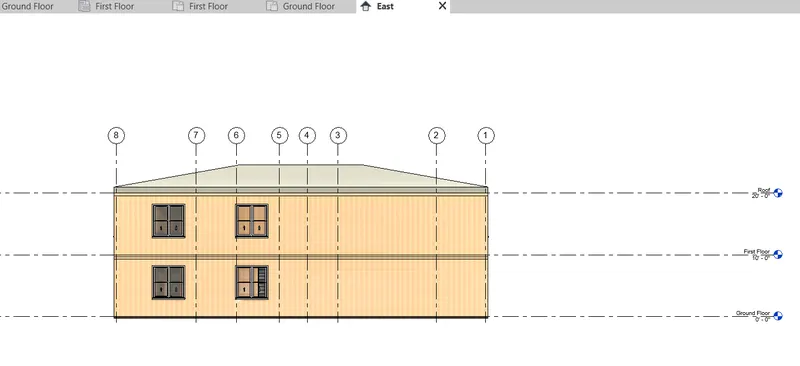
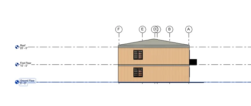
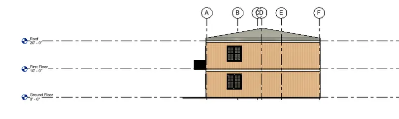
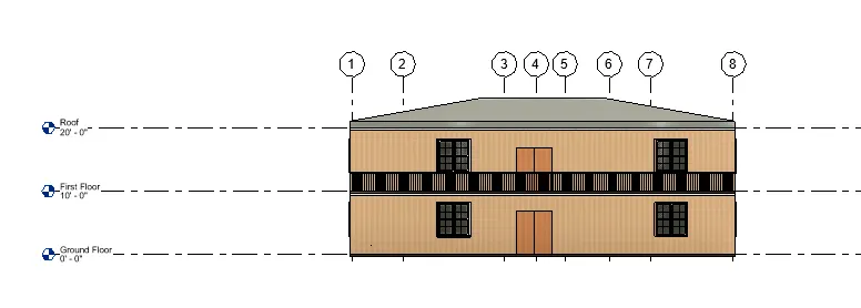
AIM :- Create the elevation view for the project.
INTRODUCTION :- The elevation view is a side view of the structure. Jim explains that an elevation is not only a side view but it is also a side view from the outside of the structure. This view can convey information that includes vertical dimensions, elevations locations of door and windows and outside finishes.
PROCEDURE :-
Creating views
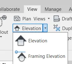
- Go to view tab in ribbon
- Click on elevation
Creating elevation points
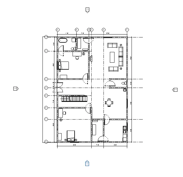
- Go to floor plan view in project browser
- Place 4 points one by one in four directions respectively
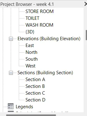
- Now in project browser building elevation will be appears
- From there you can look the elevation one by one by clicking on there names
RESULT :- Elevation views for four directions are created and each view is shown below one by one.
East
North
South
West
AIM :- To create a section cut through view either longitudinally or transverse direction.
INTRODUCTION :- A section view provides architects and contractor another way of understanding how construction will stand up as it revels details of the construction of wall and the thickness and height of beams and other supports. While a floor plan allows for a view of how the walls stand in relation to each other a section shows where the wall meets the floor and the distance that separates one floor from another.
PROCEDURE :-
Creating section lines
- Go to view tab
- Click on section
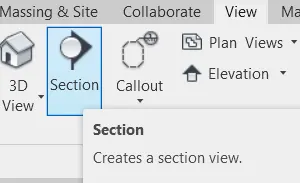
Creating sections line
- Place the curser on the one side of the section from where you want to start section
- Draw vertical or horizontal line respectively
- From where to where you need sections
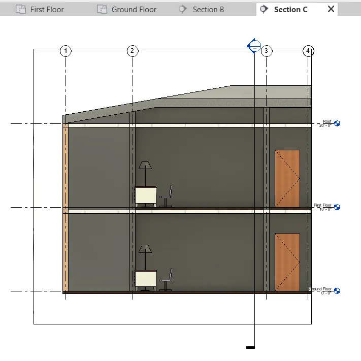
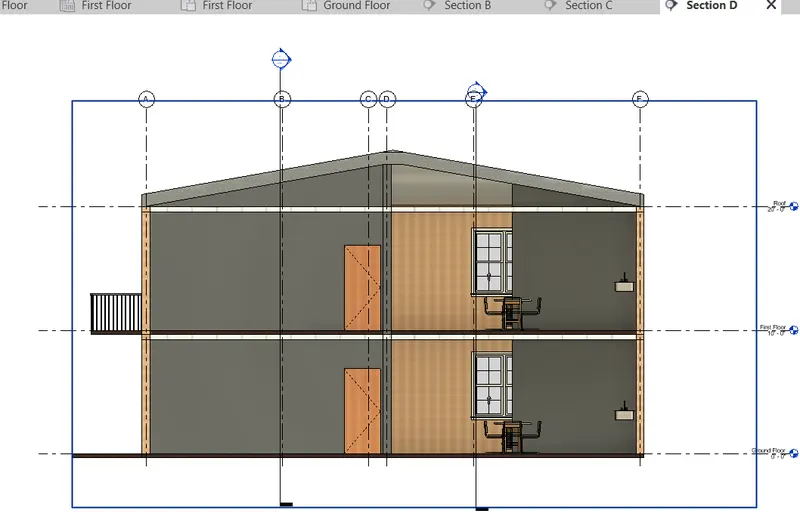
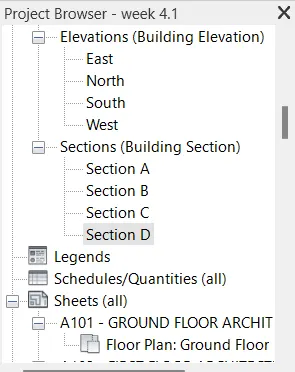
- I created sections named as A, B, C, & D
- Here they are shown
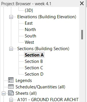
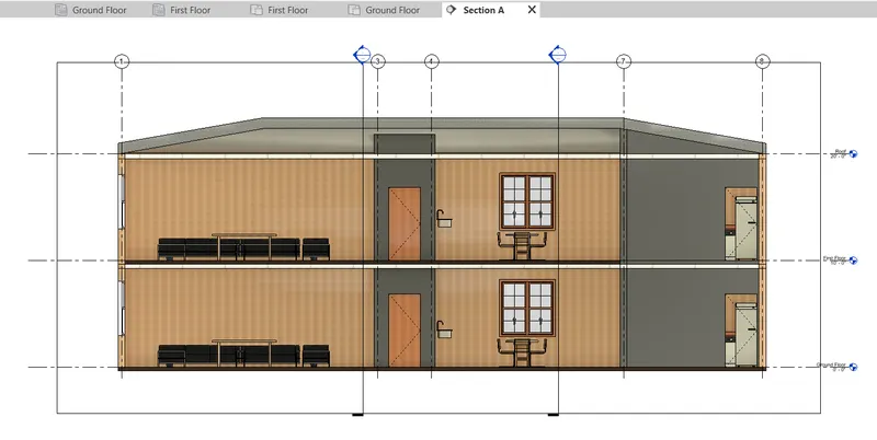
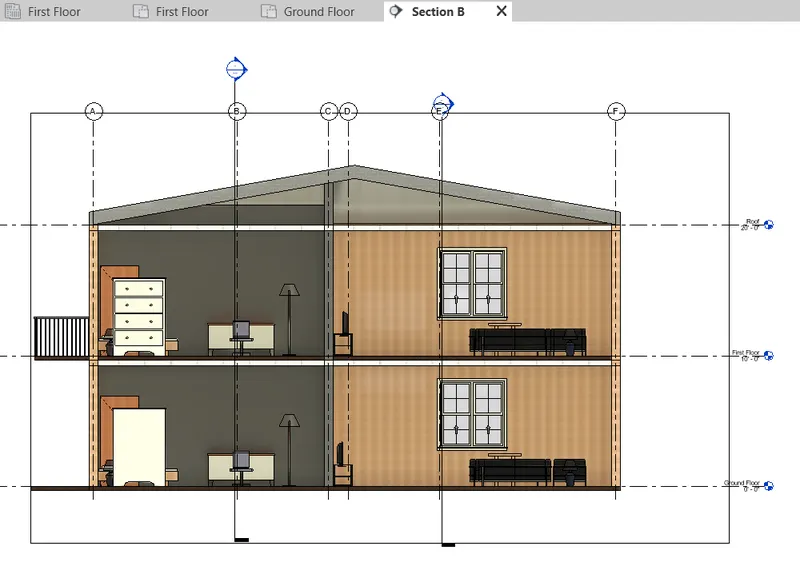
RESULT :- section of the plan is created as follow images are shown properly.
Section A
Section B
Section C
Section D
AIM :- To classify the different views from the properties browser.
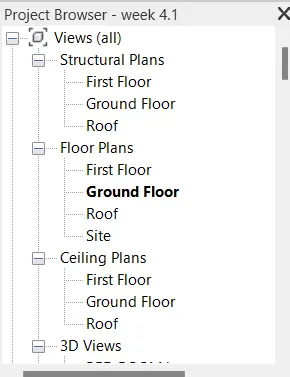
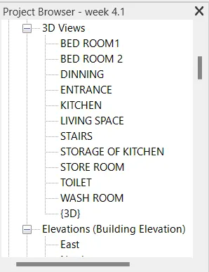
INTRODUCTION :- The view types from the properties browser is used to view the types to quickly and apply certain graphics properties and view templates to new view or to change the graphics properties for the existing views.
PROCEDURE :-
- Structural plans
- Floor plans
- Ceiling plans
- 3D-views
- Elevation (Building elevations)
- Section (Building sections)
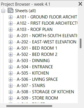
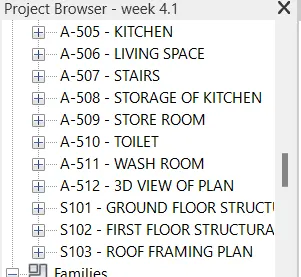
- Sheets
RESULT :- views are classified shown below briefly by using properties browsers.
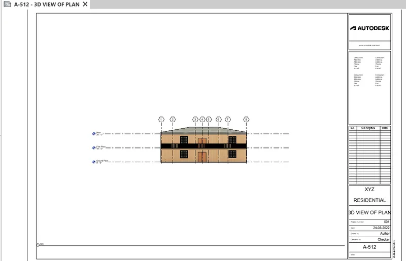
AIM :- To create multiple sheet templates for the different views of plan.
INTRODUCTION :- In Revit, you create a sheet view for each sheet in the construction document set. You can place multiple drawings or schedules on each sheet view. About sheets in project templates. Create views on project template before you start building the model to streamline the project documentation process.
PROCEDURE :-
- Go to the view tab at ribbon
- Now select the sheet option there
- Then this dialog box will appear there chose page then okay
- Then fill all the things what that sheet requires
- Then from the project browser select the ground floor and drag it to the sheets
- Then place at center then set the scale for the fit of sheet
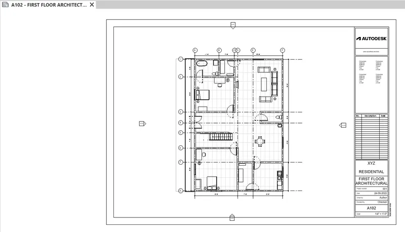
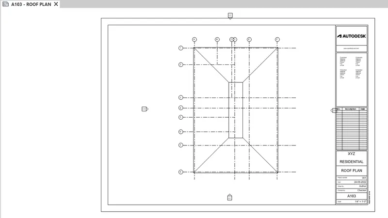
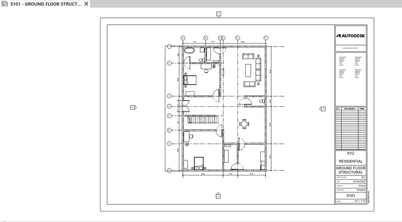
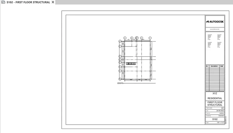
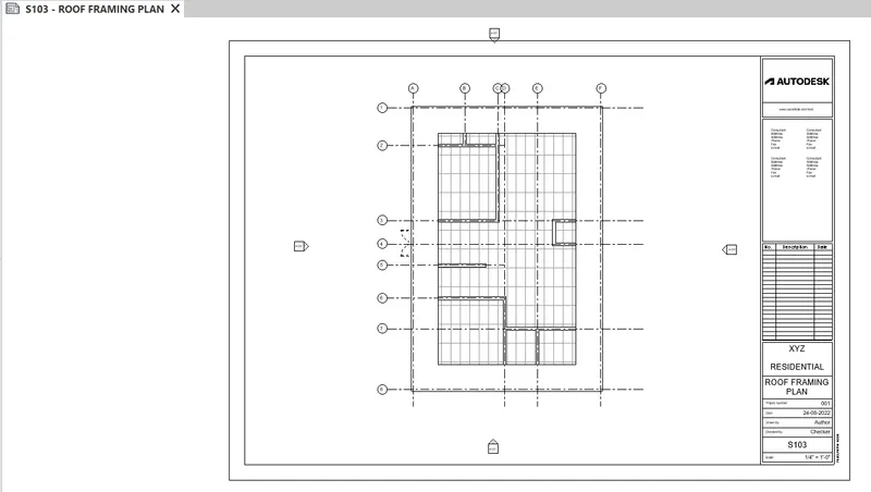
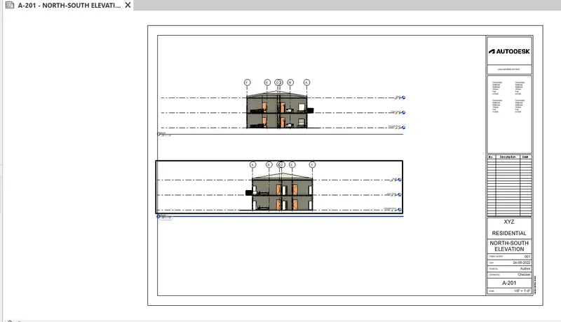
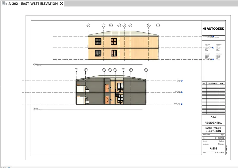
- Do same thing one by one to create the all other view template which are asked in questions and renamed them accordingly
RESULT :- All the sheet templates created with their respective views are shown below.
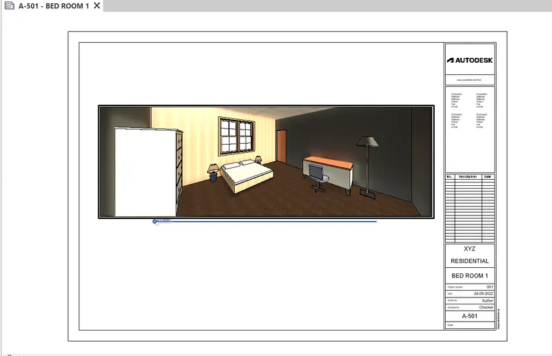
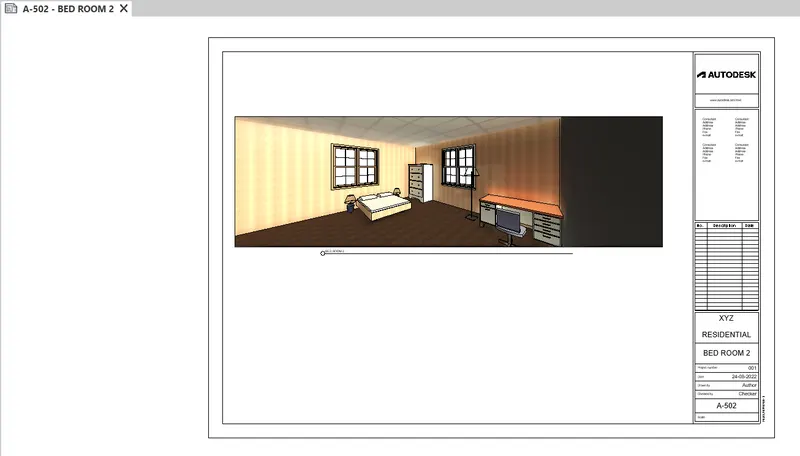
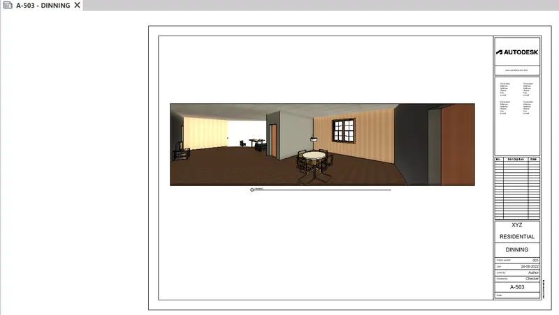
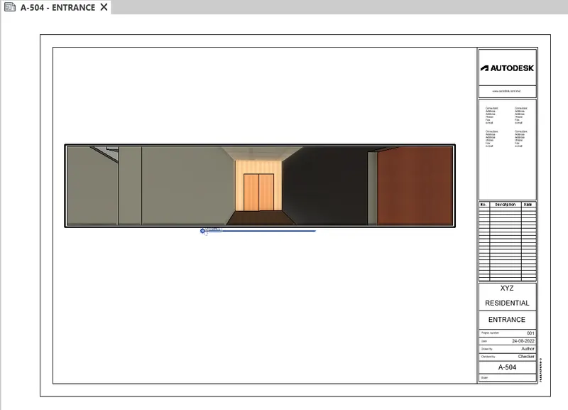
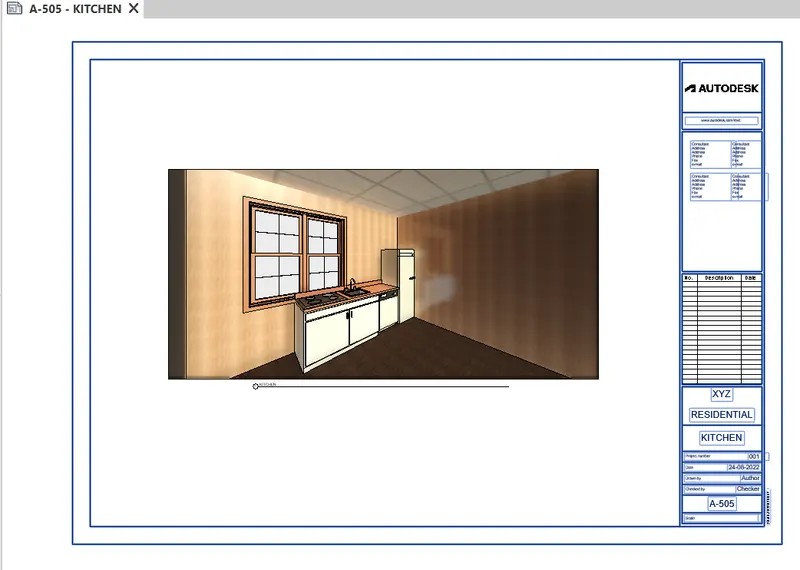
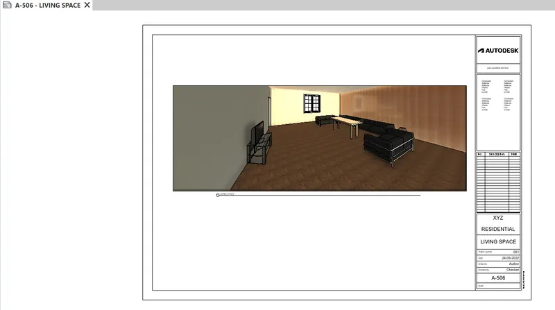
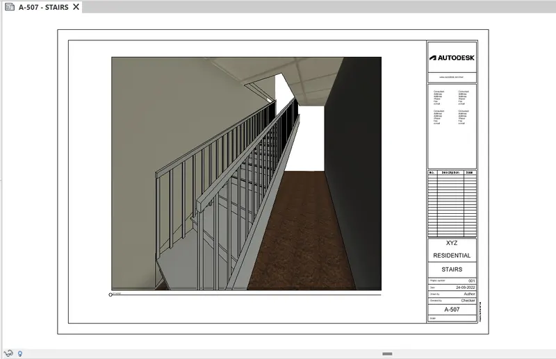
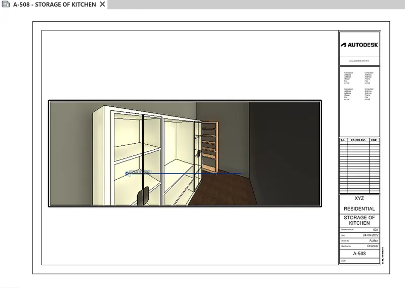
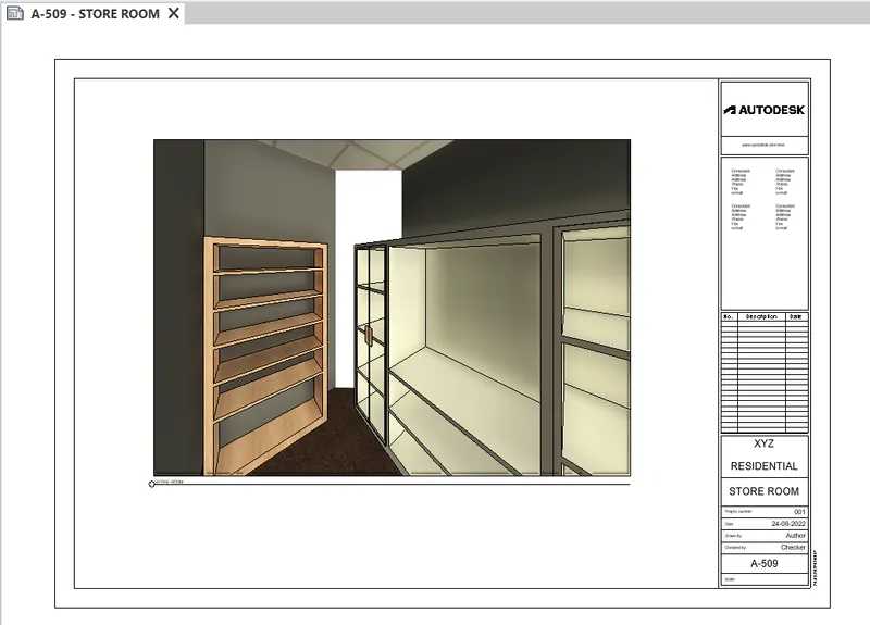
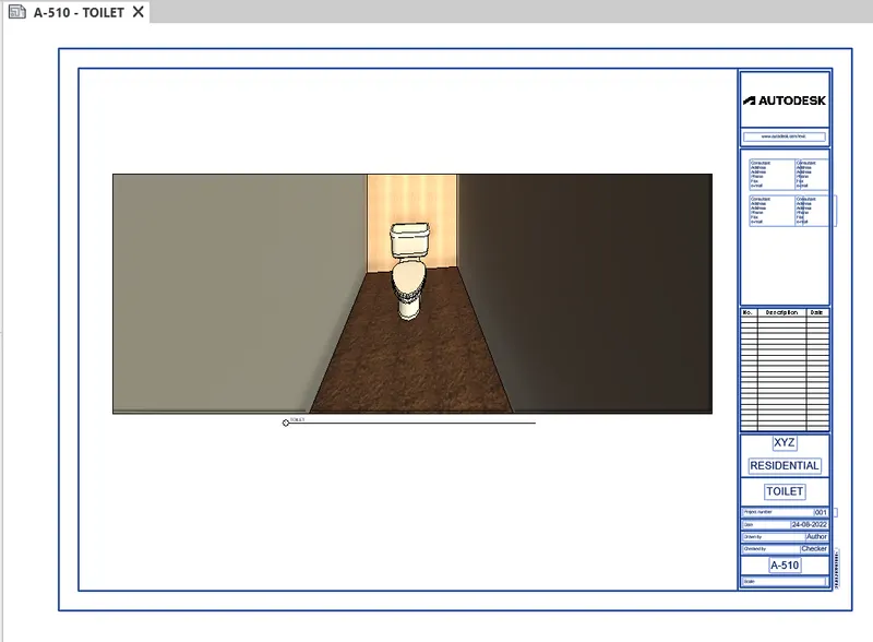
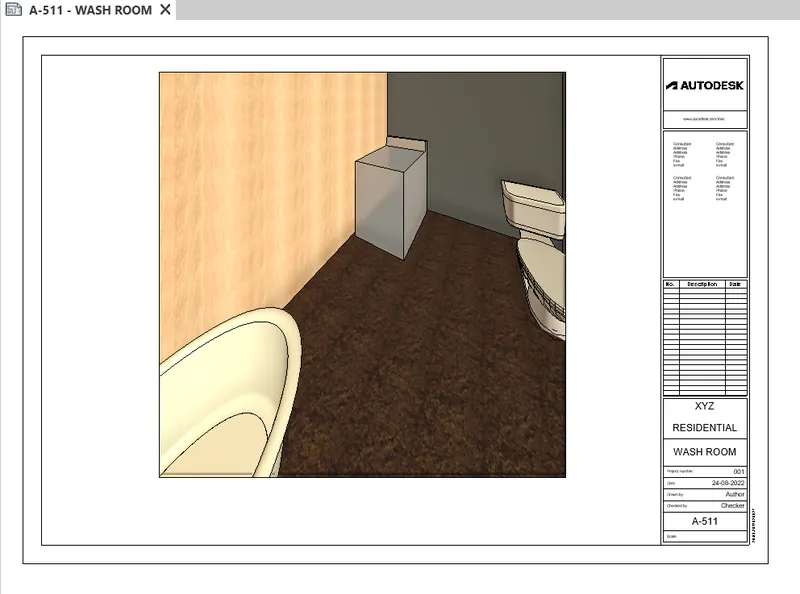
AIM :- To create multiple sheet templates for the different views of plan and place the camera to show the 3D view of the each room.
INTRODUCTION :- In Revit, you create a sheet view for each sheet in the construction document set. You can place multiple drawings or schedules on each sheet view. About sheets in project templates. Create views on project template before you start building the model to streamline the project documentation process.
PROCEDURE :-
Creating camera view
- go to the view tab in ribbon
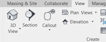
- select 3D view then select camera
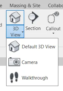
- then place the room what you want to see
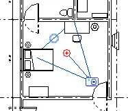
Adding view templates
- Go to the view tab at ribbon
- Now select the sheet option there
- Then this dialog box will appear there chose page then okay
- Then fill all the things what that sheet requires
- Then from the project browser select the ground floor and drag it to the sheets
- Then place at center then set the scale for the fit of sheet
- and use crop size option to set the views in template
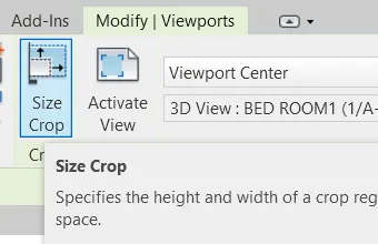
- Do same thing one by one to create the all other view template which are asked in questions and renamed them accordingly
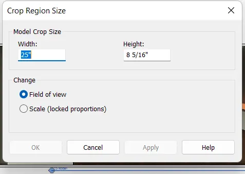
RESULT :- Following are the 3D view template of the plans.