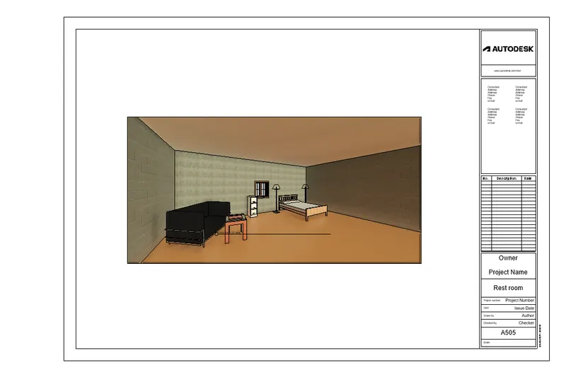
3D Creation of Celing, Roof, Architectural plan, Structural plan, Sectional view, Elevation view and Camera specific view for a house plan using REVIT
Question 1) Based on the project saved from Week 3, proceed from the First Floor Level. Model a Ceiling from the architecture tab above the walls at the first-floor level.
AIM: To model a Ceiling from the architecture tab above the walls at the first-floor level.
INTRODUCTION: Revit software allows us to create a ceiling to our project using the Architecture tab. Ceiling is the overhead surface or you can say that ceiling is a surface which covers the room. Ceilings are normally used to hide the floor and the roof construction. Ceiling creates the enclosure between the spaces. Ceilings also helps to control the sounds and the diffusion of the lights around a room.
PROCEDURE:
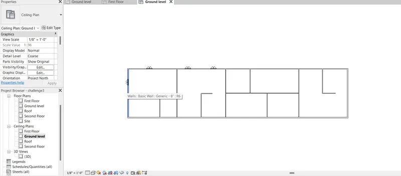
- To create a ceiling to the first floor, First of all go the the ceiling plan option in the project browser from there click on the Ground floor option. After clicking on the celings option the drawing area appears on the screen just like the below figure.
- Then go to the Architecture tab in that space there is a option called Ceiling. Just as shown in the below figure.
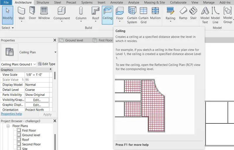
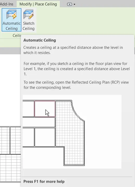
- From that option click on that tab to invoke the ceiling option in Revit software. Just click on the celing option. After clicking on the celing tab there is a new toolbar open named as Modify| Creating ceiling boundary. In that option there is a button named Automatic celing just click on that button. After clicking on that take the cursor to the drawing space and click on the rooms one by one then automatically ceiling creating on that floor we dont have to create the boundary lines if we click on that option.
- This automatic ceiling option provides us to create ceiling in a very simple way. It creates a ceiling at a specified distance above the level.
- After clicking on that option we take the cursor to the drawing area and then click whereever is required. After completeing the selection the floor level looks like as the given below figure:
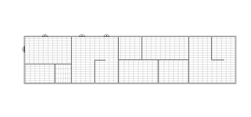
- Once the placing of the ceiling is completed just place the lightning equipments on the floor to create a realistic view on the 3D level.
- And to place the lightning components on the floor plan just follow these simple steps:
- First of all go the option Load family in the Insert tab. From there just click on the Load family option and then click just like the below figure:

- After clicking on the button Load family there is another dialouge box opens up and from that dialouge box just double click on the option US.
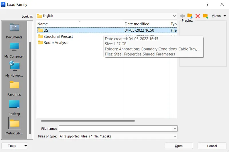
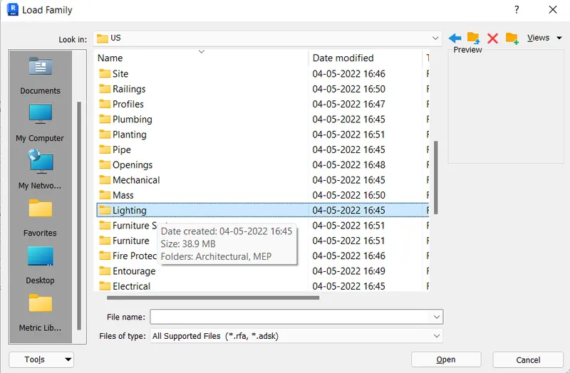
- After clicking on US another option pops up then from there double click on the Lighting button.
- And then double click on the Option Architectural.
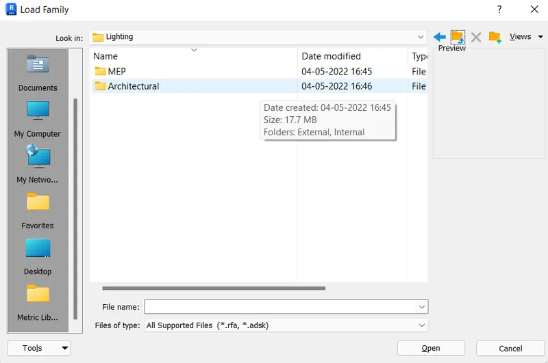
- Then double click on the Internal option, for the internal lighting and if we want to put some external lighting on our plan like in the garden or somewhere outside the house then we have to click on the external option from that option we have various options for the external lighting. But here we want the lighting for our room so that's why we need internal lights. So just double click on the Internal and that's it.
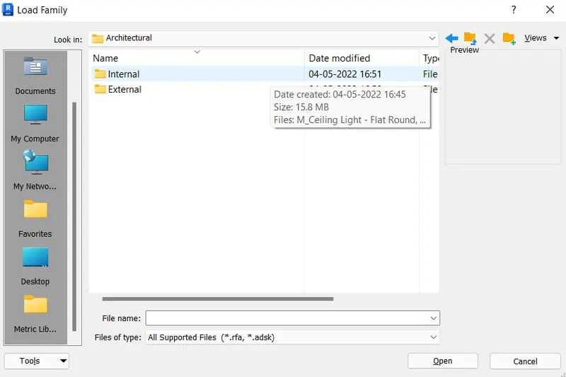
- After clicking on the Internal option we get multiple options for the internal lightings just like we will see in the below image:
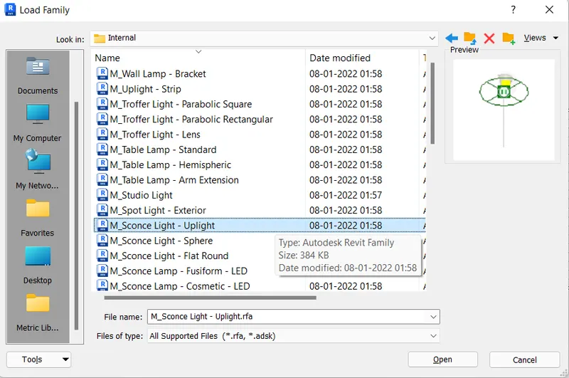
- From these muliple options we have to choose the lights as per the requirement or we can say that choose the lights as we desire.
- Just click on that light option and then press Ok.
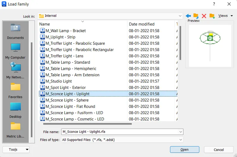
- Here we are done with choosing the lights for our plan. Repeat the same procedure for the entire rooms.
- Now after selecting the lights just place them wherever you want to put them in the plan.
- Now lets place the lights in our floor plan.
- Adjust the desired location of the lights and edit the boundaries.
- Now the ceiling is created and the lightnig also.
Question 2) Model a roof above the ceiling by selecting the footprints of the ceiling. Using the adjustment toolbars appearing on-screen adjust the roof slope to 10 degrees.
AIM: To model a roof above the ceiling by selecting the footprints of the ceiling.
INTRODUCTION: In Revit software it allolws the user to create the roof over the ceiling by selcting the footprints of the ceiling.
PROCEDURE:
- For model a roof above the ceiling level we have to go to the architectural tab and from there click on the roof tab or you can say the roof button.
- After clicking on the Roof button it will show various otions for creating a roof by different means but here we are going to create the roof using the option Roof By Footprint as shown in the below figure:
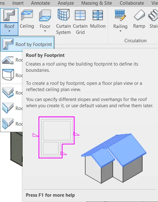
- Exactly this is how we select the option Roof by footprints.
- And after selecting the option roof by footprints, there is another dialouge box named as Lowest Level Notice and in that dialouge box they asked you have created the roof on the lowest level. Would you like to move it to another level. And from that dialouge box just click on the highest level or you can say that click on the Roof level and then click on the Yes option. This will shown exacltly like the below image:
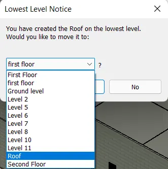
- After this select the boundaries of the walls using the Modify|Create Roof Footprint option and then select the wall boundaries using the line option just exactly shown in the below image:
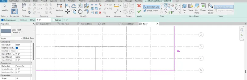
- Now create the boundary using the line command after selecting the wall click on the check option and after that the boundary for the roof is created.
- Now go to the 3D view to see the roof created.
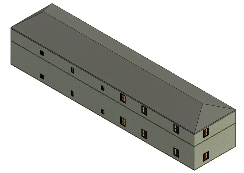
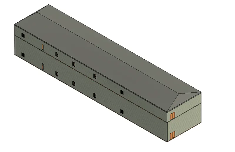
- Now this is the roof which is created using the option Roof by footprint.
- Here we have to change the slope of the roof.
- In order to change the slope of the roof just change the slope in the Properties option and from there is an option called Slope from there we can change the slope to 10'.
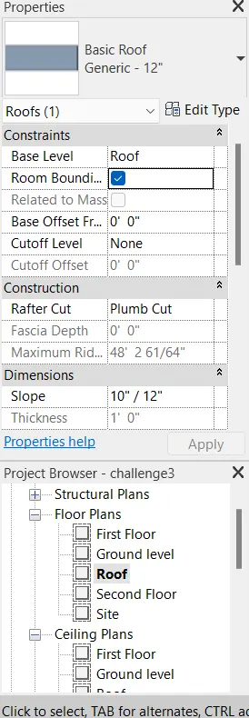
- Now the slope of the roof is changed by 10 degrees.
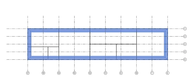
- And the roof is ready. The image is given below:
- This is the 2D image.
- And this is the 3D image.
Question 3) Using the file saved from weeks 2 to 4, create plan views for ground floor level and first-floor level including all the walls, floors, and components. Separate them to architecture and structural plans.
AIM:
- To create the plan views for the ground floor level and first floor level including all walls,floors and components.
- To separate them into architectural and structual plans.
INTRODUCTION: Revit software allows us to create the plan views in a very easiest way.
PROCEDURE:
- And to create the plan views for the ground level and the first floor level.
a) Architectural plan view:
- For creating the Architectural plan view first of all go to the View tab and from the view tab there is an option called Plan views. Click on that plan option there are various options in the plan view button. We have to click on the option Floor plan and after that the Architectural plan view is created.

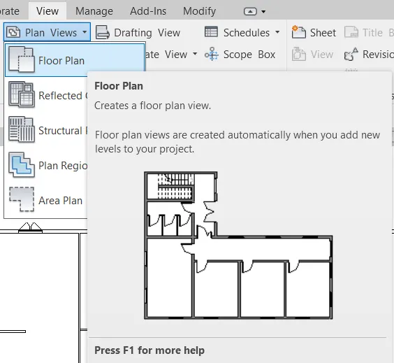
- Just as shown in the below figure:
- Ground Floor:
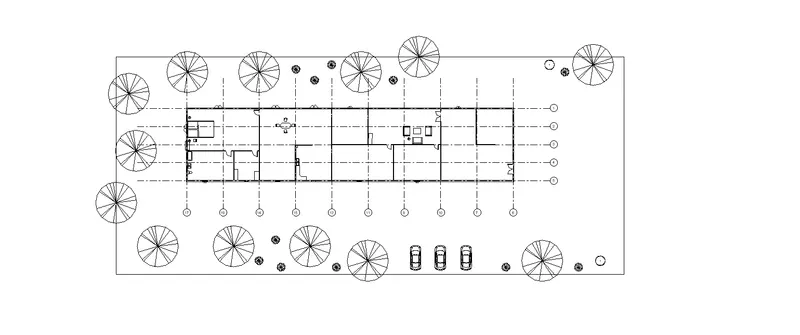
- First Floor:
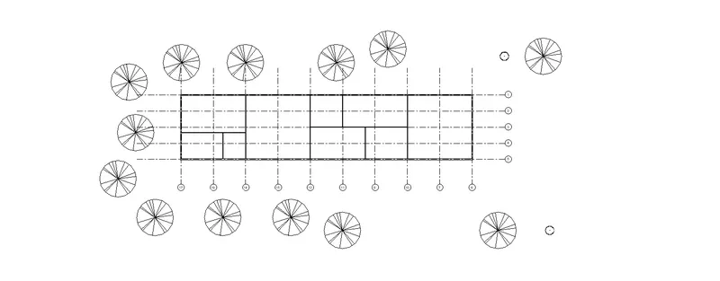
b) Structural plan view:
- Structural plan is a plan in which it shows the foundation of the building, floor of theplan and the roof plan. This plan contains the information about the structural elements present in the plans.
- For creating the Structural plan view first of all go to the View tab and from the view tab there is an option called Plan views. Click on that plan option there are various options in the plan view button. We have to click on the option Floor plan and after that the structural plan view is created.
- So just shown in the below image:
- After this just duplicate the architectural plan into the another floor plan.
- In order to create the structural plan first of all we have to duplicate the existing plan and named as Ground floor structural plan just as the below figure:
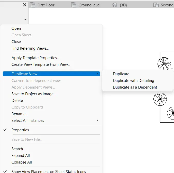
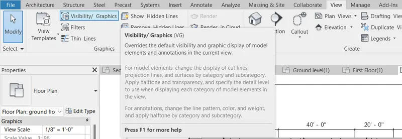
- After duplicating the plan, go to the option visual and graphics in the View toolbar. As shown in the below image:
- After clicking on that option there is another dialouge box opens named as Visual graphics so from there just uncheck the unnecessary option in order to create the structural plan view. For example doors,windows,furniture etc. Just as shown in the below image:
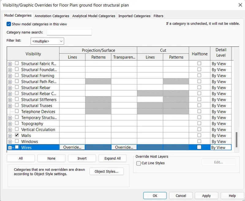
- After this step we can create the ground floor structural plan. Below are the images of the structural plan for the ground floor and the first floor.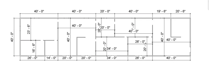
- Ground Floor:
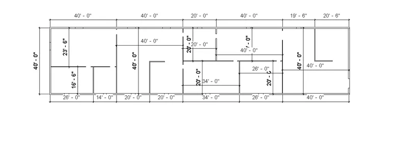
- Now the structural and the architectural plan view has been created. Just follow the simple above steps after following those steps we can draw the plan views in different views i.e Architectural and structural view.
Question 4) Using annotate toolbar add dimensions to all the walls and floors with reference to the longitudinal and transverse grids created in the project file
a. The architecture plan dimensions include details on where the components are placed within the buildings with relation to grids. Overall dimensions are sufficient for architecture plans
b. The Structure plan dimensions must include details on the position of all the walls and interior walls with reference to grids. Locate all the framing components of the building with reference to a fixed point using Structural plans.
AIM: To add the dimensions to all the walls and the floors with reference to the longitufinal and the transverse grid created before.
INTRODUCTION: Revit software provides us to annotate oiur floor plan with the help of different options present in the software. There are aligned dimensions,linear and angular dimensions etc. We can annotate the different elements by using these options. So lets get started.
PROCEDURE:
(a) The architecture plan dimensions include details on where the components are placed within the buildings with relation to grids. Overall dimensions are sufficient for architecture plans:
- To created the dimensions on the architectural plan.
- First of all go to the Annotate Tab from there click on the Aligned dimension tab or just type DI. Here is the image showing the annotate tab and the aligned option or button:
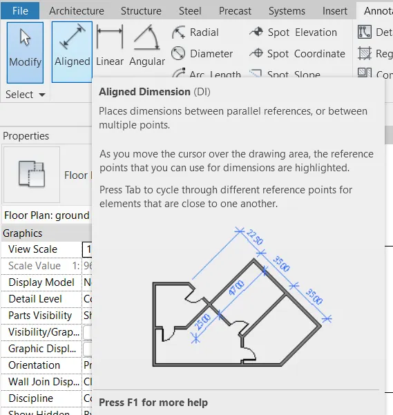
- Now after selecting this option or after selecting the aligned option/button from the annotate tab we can start dimensioning the architectural plan.
- But before that duplicate the ground plan just by clicking the right click on the ground floor plan and rename it as Ground Floor plan 2. Here is the image to show the how we can duplicate the image:
- And after duplicationg the ground floor and the first floor plan we can start the dimensioning in the Architectural plan.
- Just click on the aligned option from the annotate tab and then start dimensioning.
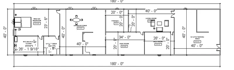
- The architecture plan dimensions include details on where the components are placed within the buildings with relation to grids. Overall dimensions are sufficient for architecture plans.
GROUND FLOOR ARCHITECTURAL VIEW:
FIRST FLOOR ARCHITECTURAL VIEW:
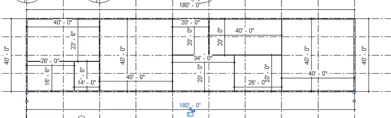
(b) The Structure plan dimensions must include details on the position of all the walls and interior walls with reference to grids. Locate all the framing components of the building with reference to a fixed point using Structural plans.
- To created the dimensions on the structural plan.
- First of all go to the Annotate Tab from there click on the Aligned dimension tab or just type DI. Here is the image showing the annotate tab and the aligned option or button:
- Now after selecting this option or after selecting the aligned option/button from the annotate tab we can start dimensioning the structural plan.
- But before that duplicate the ground plan just by clicking the right click on the ground floor plan and rename it as Ground Floor plan 3. Here is the image to show the how we can duplicate the image:
- And after duplicationg the ground floor and the first floor plan we can start the dimensioning in the Structural plan.
- Just click on the aligned option from the annotate tab and then start dimensioning.
- The Structure plan dimensions must include details on the position of all the walls and interior walls with reference to grids. Locate all the framing components of the building with reference to a fixed point using Structural plans.
GROUND FLOOR STRUCTURAL VIEW:
FIRST FLOOR STRUCTURAL VIEW:
Question 5) Create a sheet template from the view tab and adjust the parameters on the sheet to add appropriate views.
AIM: To create the sheet template from the view tab and adjust the parameters on the sheet to add appropriate views.
INTRODUCTION: Revit software allows the user to create the templete of their own or the users can use the template provided within the software which is already available in the Revit software. So here we will learn how to create the template in the software using the Template option present in the software alredy. So let's get started.
PROCEDURE:
- So first of all to create the template in the drawing sheet or in the project.
- We need to go to the view tab after clicking on the view tab just click on the option sheets as shown in the below image:

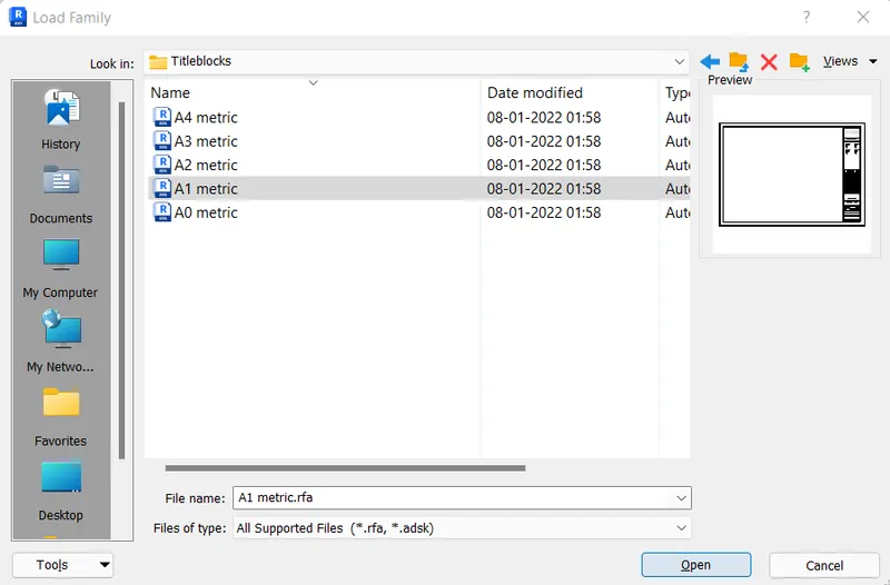
- After clicking on the option sheet from the view tab, a new dialouge box opens up called New Sheet. In that dialouge box just click on the load button after clicking on the load button the family dialouge box opens up as shown in the below figure:
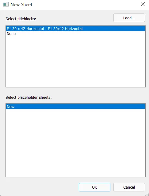
- In that dialouge box just click on the load button after clicking on the load button the family dialouge box opens up.
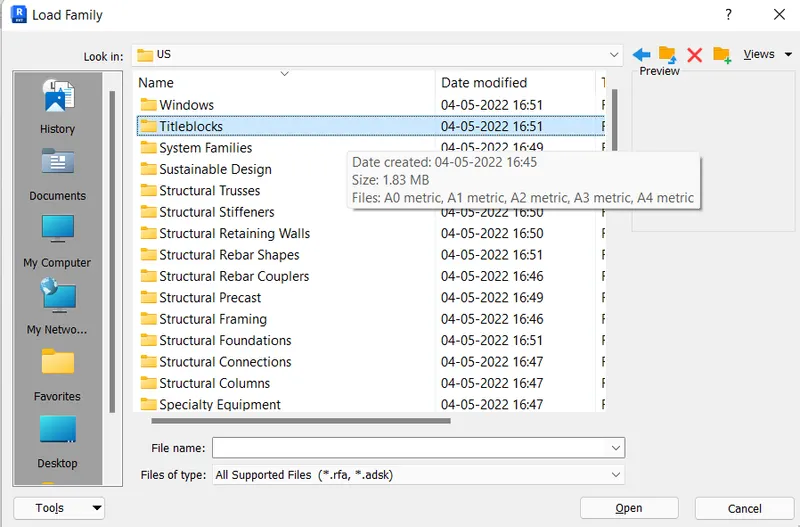
- In that dialouge box just click on the option Titleblocks.
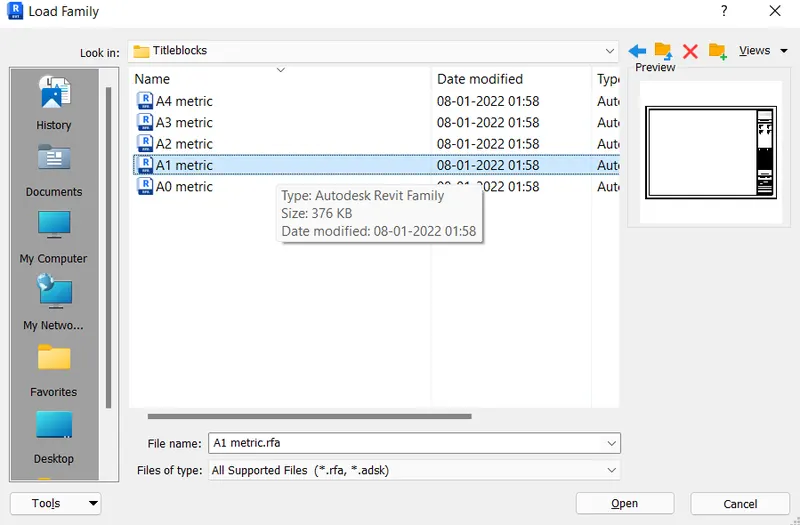
- In this there are various number of sheets present with different sizes. From here we have to choose the sheet according to our project requirement.
- Here i have choose A1 Metric and then click on the option Open.
- And after clicking on the Open option. There is another dialouge box opens called new sheet. In that dialouge box the selected Titlebar is added on that dialouge box just as shown in the below figure:
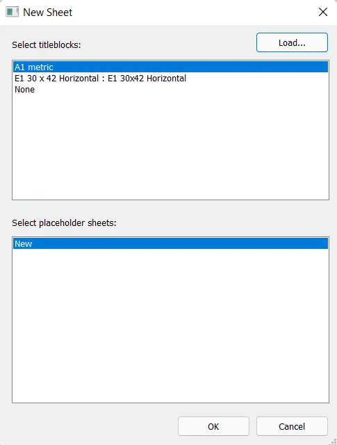
- And then click on the Ok option.
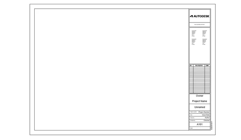
- After clicking on the OK option this sheet of A1 size added on the drawing sheet.
- After adding the sheet we can add the views on this sheet using the view option from the View toolbaar. Just as shown in the below image :

- After clicking on the view option there is another dialouge box opens up from there we have to select the view option which we are desired to put on that sheet as shown in the figure:
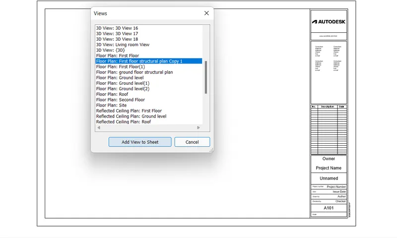
- Now select the views from this diaoluge box and then press Add view to sheet.
- Now that view which we have selected before is added on the sheet just like the below image:
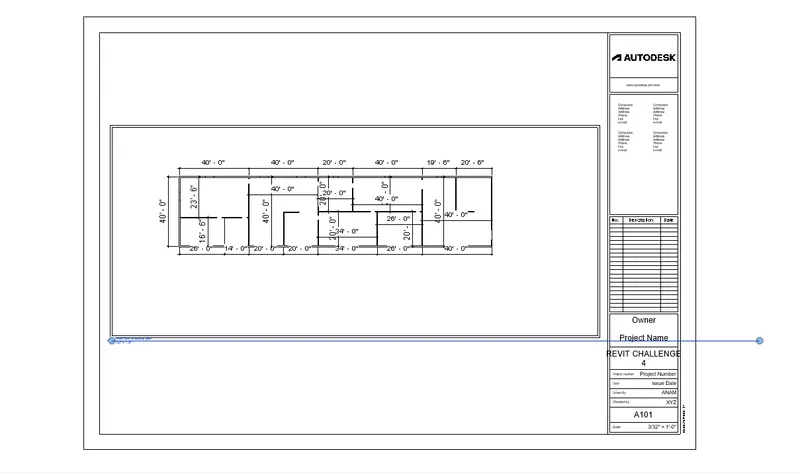
- In this way we can add the template to our projects. And we can also edit the details on the sheets.
- So here is the final result:
Question 6) Using the elevation tab create the elevation views, looking at your building from East, North, South, and West.
AIM: To create the elevation views, looking at the building from East, North, South, and West.
INTRODUCTION: Revit software is a software which allows the user to create the elevation of the building in a very easy manner. Here we will get to know about the elevation created by the software. So let's get started.
PROCEDURE:
- So first of all to create the elevation of the building,what we have to do is to click on the View tab and in the view tab there is an option called Elevation. And from there only we have to click on the Elevation button. Just as shown in the below image:
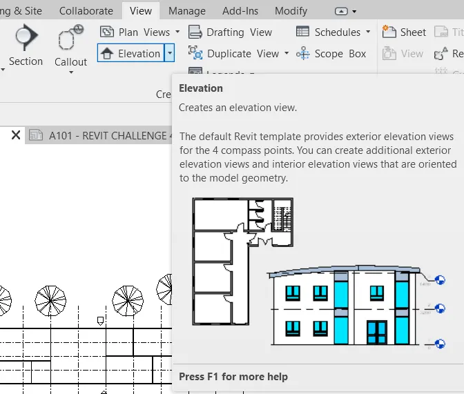
- After clicking on the elevation option. Go to the property browser from there click on the Elevation and from there a arrow like thing appears on the screen. So keep the arrow in the direction in which we want to create our elevation.
- In this question i want to create the elevation in all the directions like North,East,West and South.
- For this we have to keep the pointer in all the four sides of the plan just as shown in the below figure.
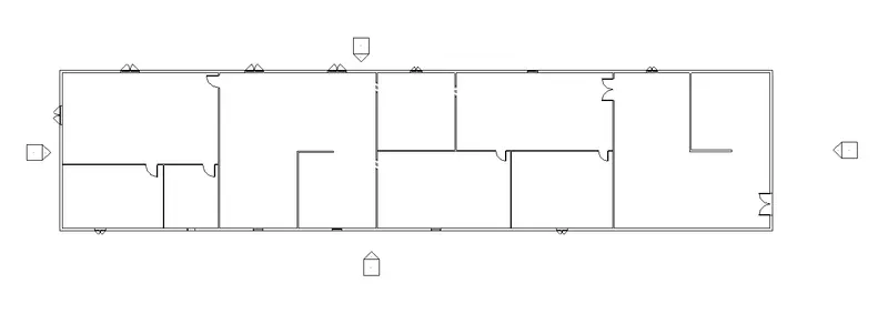
- After this just go to the project browser and created on the Elevation option. As shown in the below figure:
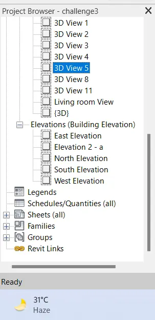
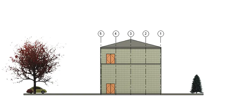
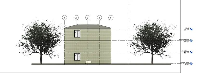
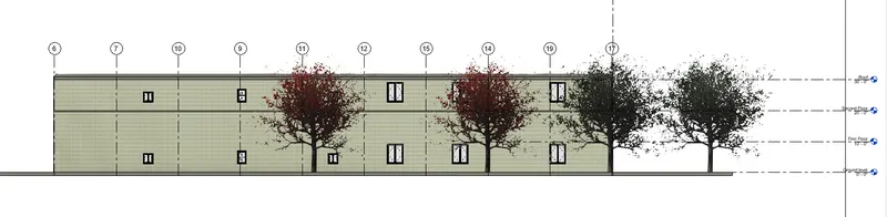
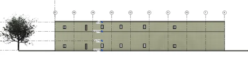
- Then the Elevations of the building for all the four sides has been created.
- North Side Elevation:
- South Side Elevation:
- East Side Elevation:
- West Side Elevation:
- These are all the four sides of Elevation of the building using the Revit software.
Question 7) Produce section cut through each room either cutting across longitudinally or in a transverse direction.
AIM: To cut through the sections through each room either cutting across longitudinally or in a transverse direction.
INTRODUCTION: Revit software allows the user to create the sections in a very easy manner. Section is nothing but the view seen by cutting the half of the building or cut through the imaginary plane known as the section lines, which may be in vertical as well as in horizontal direction it depends. So here we will thoroughly learn about the section, how to cut the building, how to provode the section line and many more. So in order to understand this thoroughly lets get started.
PROCEDURE:
- So first of all go to the View tab from there go to the section option and click on that option. As shown in the below image:
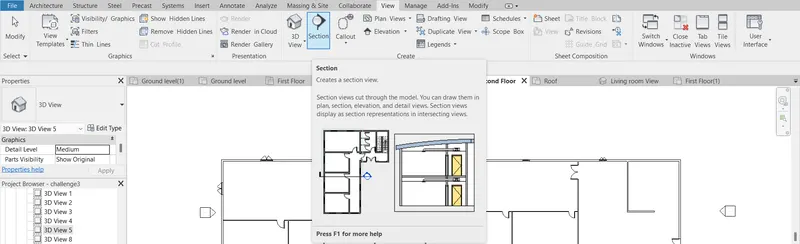
- After clicking on the section button,add a section to the bedroom and the bathroom. As shown in the below figure:
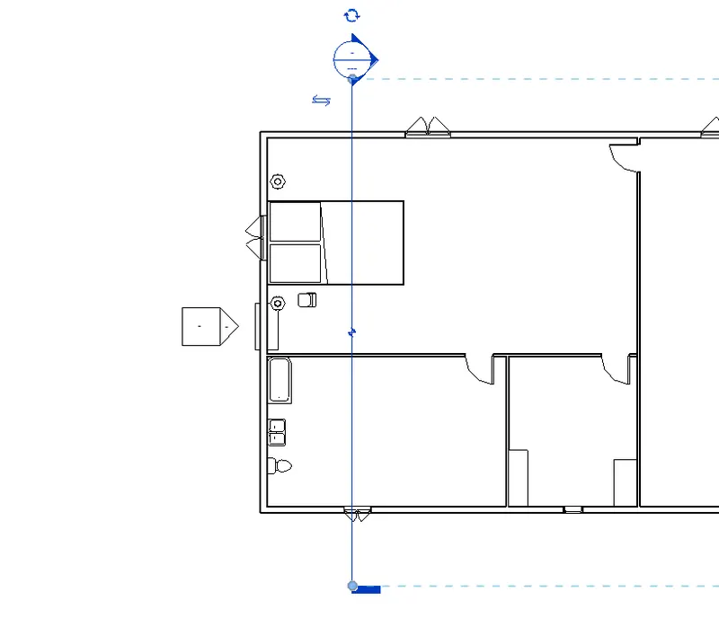
- You can adjust the section line through dragging the dotted lines.
- And the sections are seen in the project browser area. From project browser area we can edit the sections also.
SECTION 1 BEDROOM AND TOILET:
- This is the result of section through the bedroom and the toilet.
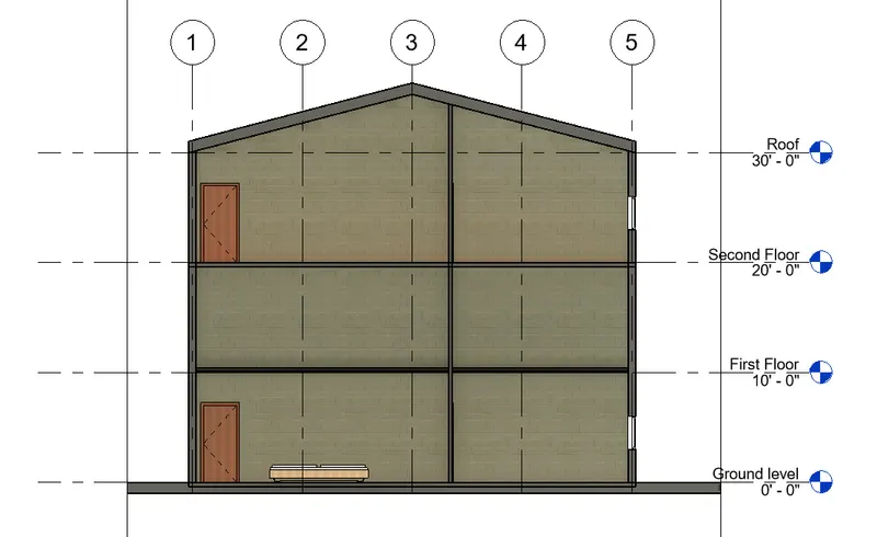
- We repeat the same procedure for all the sections which we are going to create.
- Now for the other sections follow these steps.
SECTION 2 LIVING ROOM AND KITCHEN:
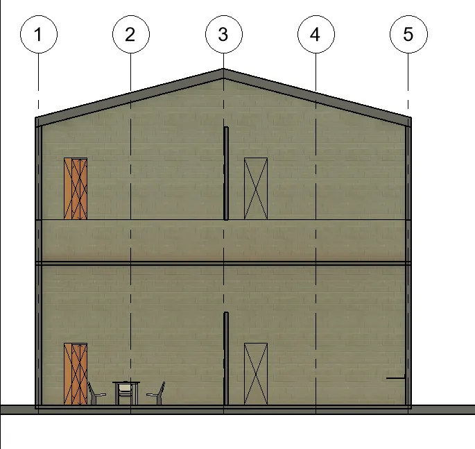
SECTION 3 PRAYER ROOM AND KIDS ROOM:
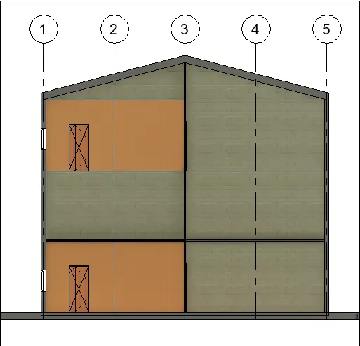
SECTION 4 LIVING ROOM AND REST ROOM:
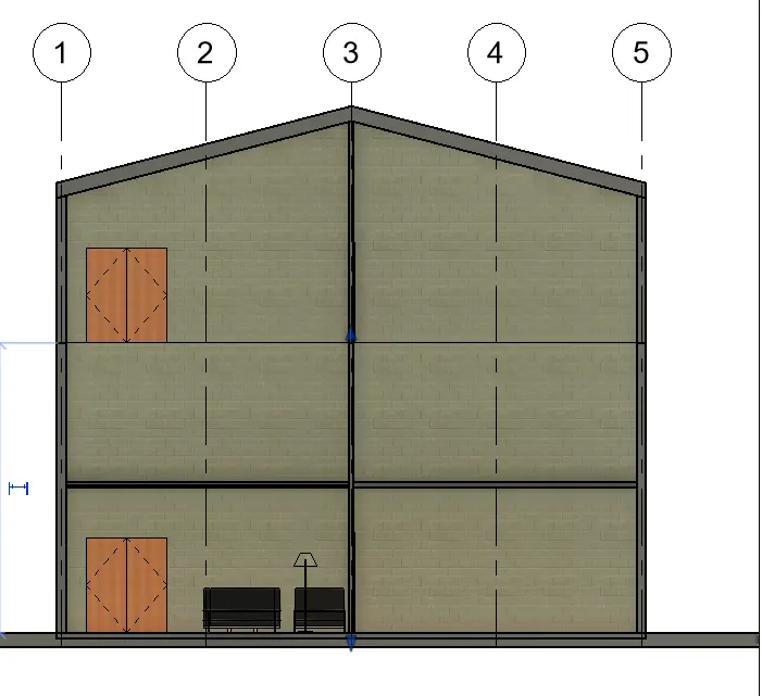
Question 8) Classify the views, Plan Views, Section Views, and Elevation views to either Design or Documentation category using Properties browser.
AIM: To Classify the views, Plan Views, Section Views, and Elevation views to either Design or Documentation category using Properties browser.
INTRODUCTION: In this qestion we will learn about thr design or the documentation category using the property browser.
PROCEDURE:
PLAN VIEWS:
GROUND FLOOR ARCHITECTURAL VIEW:
FIRST FLOOR ARCHITECTURAL VIEW:
GROUND FLOOR STRUCTURAL VIEW:
FIRST FLOOR STRUCTURAL VIEW:
ROOF FLOOR PLAN:
ELEVATION VIEWS:
- North Side Elevation:
- South Side Elevation:
- East Side Elevation:
- West Side Elevation:
SECTION VIEWS:
SECTION 1 BEDROOM AND TOILET:
- This is the result of section through the bedroom and the toilet.
- We repeat the same procedure for all the sections which we are going to create.
- Now for the other sections follow these steps.
SECTION 2 LIVING ROOM AND KITCHEN:
SECTION 3 PRAYER ROOM AND KIDS ROOM:
SECTION 4 LIVING ROOM AND REST ROOM:
Question 9) Using the sheet template produced create multiple sheets as follows
a. A 101- Ground Floor Architecture Plan
b. A 102- First Floor Architecture Plan
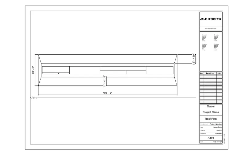
c. A 103- Roof Plan
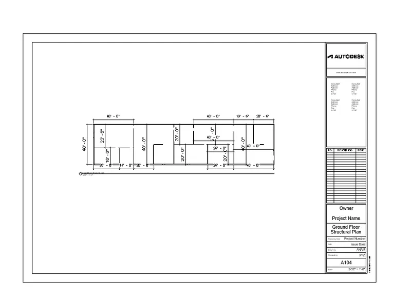
d. S 101- Ground Floor Structural Plan
e. S 102- First Floor Structural Plan
f. S 103- Roof Framing Plan
g. A-201- North-South Elevations
h. A-202- East-West Elevations
Add additional sheets based on the sections created in your Revit file.
AIM: To create the multiple sheets using the sheet template.
INTRODUCTION: Revit software allows the user to create the templete of their own or the users can use the template provided within the software which is already available in the Revit software. So here we will learn how to create the template in the software using the Template option present in the software alredy. So let's get started.
PROCEDURE:
- In order to create the different sheets we have to go to the View tab and from the view tab there is an option called Sheets just click on that as shown in the below figures:

- After clicking on this sheet button, a sheet appears on the screen after we had done choosing the size of the sheet. As shown in the below figure:
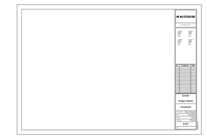
- This is the new sheet created using the sheet option on the View Tab.
- So after creating the sheet we have to create sheets with different first floor plan,ground plan and the roof plan.
- So first of all lets create the sheet for the ground floor architectural plan.
(a) A 101- Ground Floor Architecture Plan:
- In order to create the ground floor architecture plan first of all we have to create the sheet as we have done in the above steps for creating the sheets.
- After creating the sheet we have to put the Ground floor Architectural plan. So for this we have to go to the project browser from the project browser go to the option Floor plans and from there click on the ground floor architectural plan and then drag the file to the sheet and thats it.
- After that adjust the scale according to the size of the sheets.
- And here we are done.
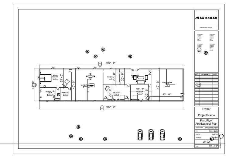
- Now here is the result given for the ground floor architectural plan:
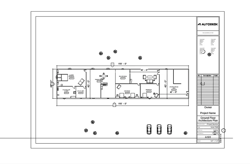
- Repeat the same procedure for all the sheets.
(b) A 102- First Floor Architecture Plan
(c) A 103- Roof Plan
(d) S 101- Ground Floor Structural Plan
(f) S 103- Roof Framing Plan
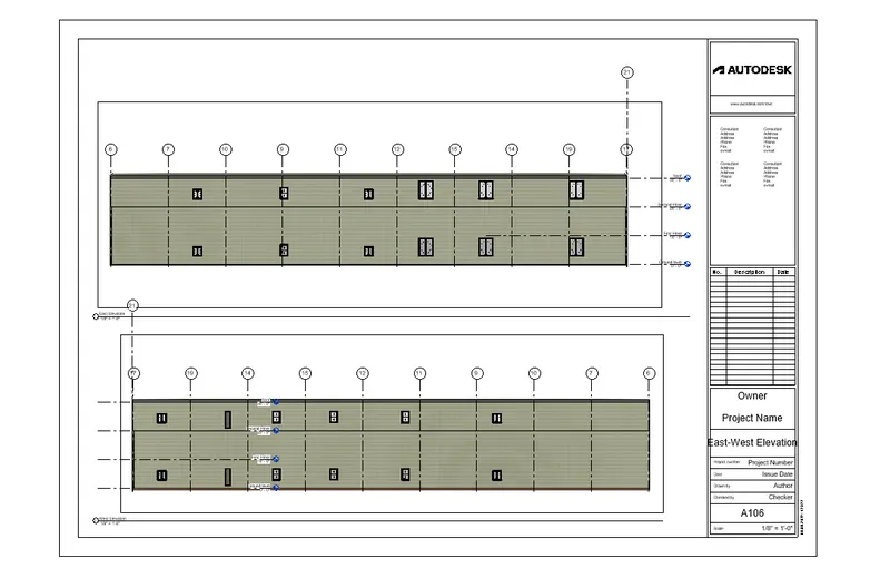
(g) A-201- North-South Elevations
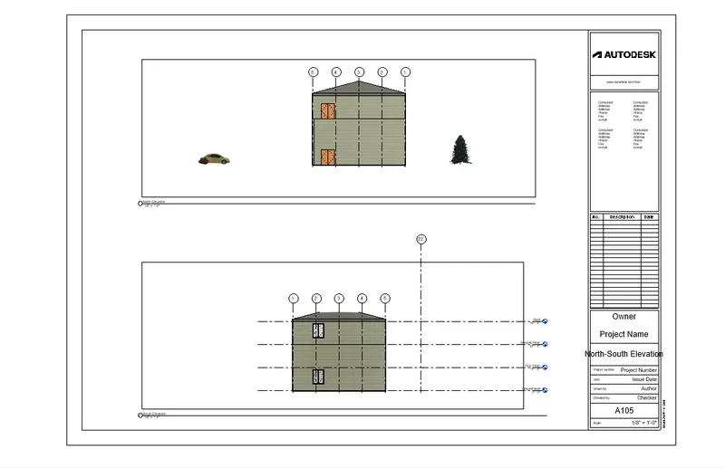
(h) A-202- East-West Elevations
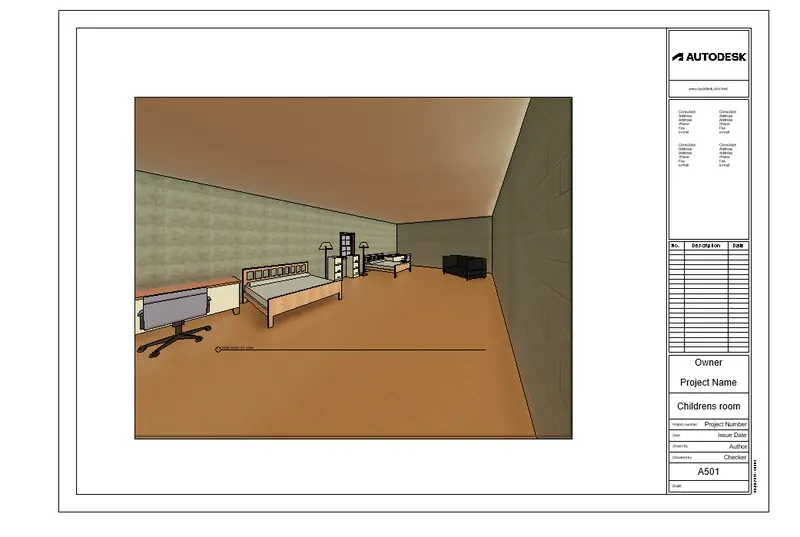
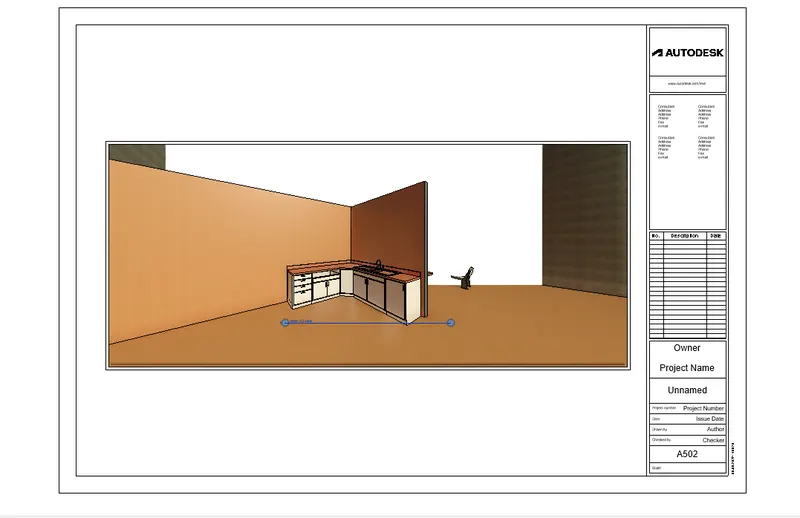
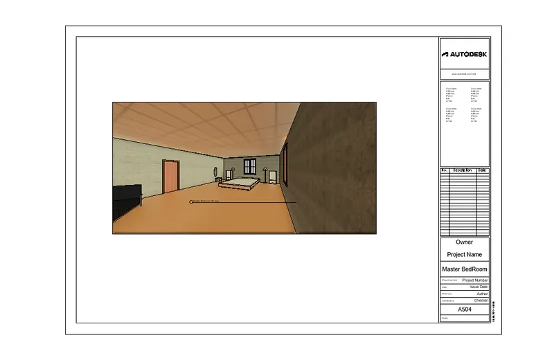
Question 10) Create a camera-specific view or a 3D view in each room ( living, dining, bedroom). Based on the views create a new set of sheets starting A-501 (you can add as many sheets after, 502, 503.. n)to place the 3D view images. Produce the sheets as a part of project drafting.
AIM: To create a camera-specific view or a 3D view in each room ( living, dining, bedroom).
INTRODUCTION: Revit allows the user to create its own 3D. In this we will learn about the 3D views and its usage in the software.
PROCEDURE:
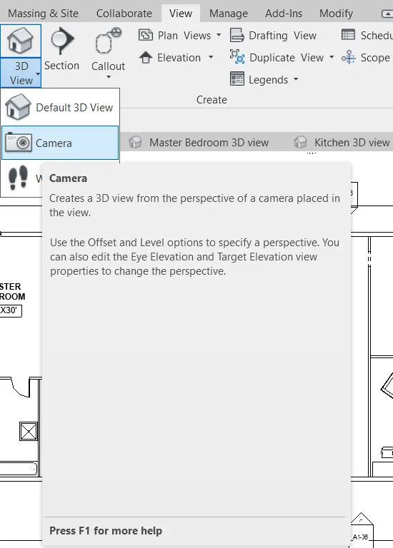
- In order to create a camera-specific view or a 3D view in each room ( living, dining, bedroom) we need to go to the view tab and from that tab we need to click on the 3D option in that option we find 3 more option and from that option we need to click on the Camera option. Just as shown in the below figure:
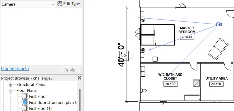
- After clicking on the camera option we need to specify the location of the camera. From where we want to take the picture at what angle and all. We need to specify that just as seen in the below image:
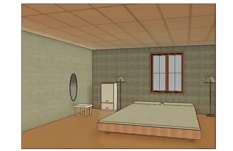
- After placing the camera at the desired location then it will automatically created the 3D image as shown in the below figure:
- Now repeat the same procedure for all the rooms.
(a) Children's Room:
(b) Kitchen:
(c) Master Bed Room:
(d) Rest Room: