2D Shell Meshing of the CAR side door inner panel for component level analysis using FEA tool Hypermesh
Aim of Project - 2D Shell Meshing of the CAR side door inner panel for component level analysis using FEA.
Objective of Project - To perform the necessaty geometry cleanup and meshing car side door inner panel using the FEA tool HYPER-MESH.
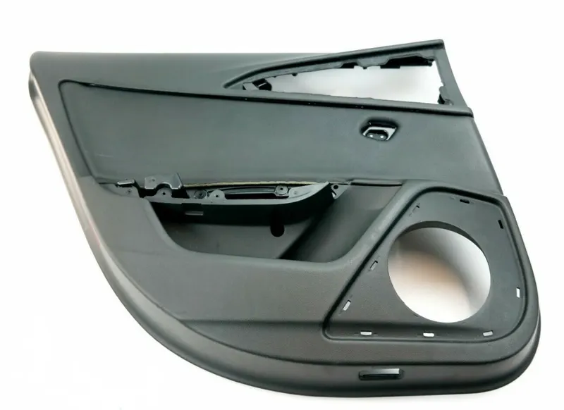
Why do we carry out Meshig?
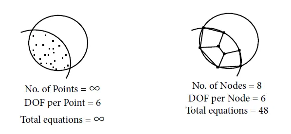
The basic idea of FEA is to make calculations at only limited (Finite) number of points and then interpolate the results for the entire domain (surface or volume). Any continuous object has infinite degrees of freedom and it's just not posiible to solve the problem in this format. Finite Element Method reduces the degree of freedom from ifinite to finite with the help of discretization or meshing (nodes and elements).
Meshing is an integral part of the engineering simulation process where complex geometries are divided into simple elements that can be used as discrete local approximations of the larger domain. The mesh influences the accuracy, convergence and speed of the simulation. Furthermore, since meshing typically consumes a significant portion of the time it takes to get simulation results, the better and more automated the meshing tools, the faster and more accurate the solution.
2D meshing is carried out on a mid surface of the door panel parts. By creating 2D elements, the softwae knows 2 out of the 3 required dimensions, The third dimension, thickness, is been provided by the user as an additonal input data.
Why is 2D Meshing carried out on a Mid Surface?
Mathematically, the element thickness specified by the user is assigned half on the element top and half on the bottom side. Hence, in order to represent the geometry appropriately, it is necessary to extract the midsurface and the mesh the surface.
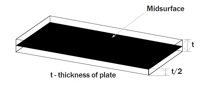
The same manner below is the procedure explaining one by one how the mid suface is extraced on each components and how it meshed with the gives quality criteria. After performing the meshing the thikneess is assigned by the user to represnt the geometyr as in real scenario.
Procedure -
Step I - Import the geometry i.e, the .hm file (extension)using the file tab in the HYPER-MESH window.
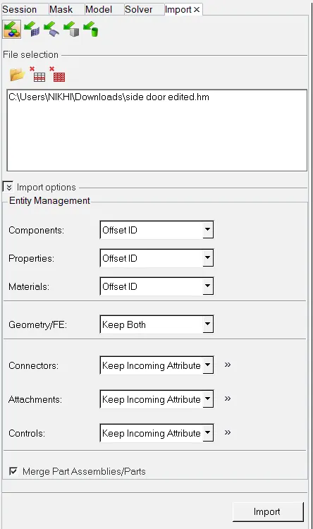
Step II - After importing the geometry, switching to the topo module. After this one by one, the component is identified as below
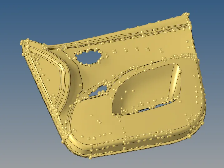
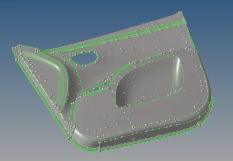
fig - Imported Geometry fig - Topo Mode
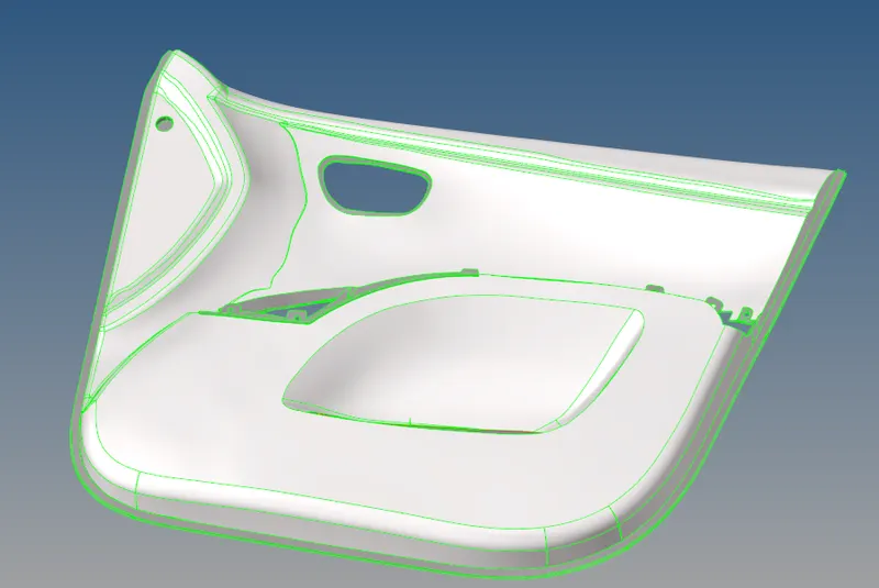
The user identify each component by verifying the geomerty and takes out the midsurface one by one for all the important featutes and make the component list.
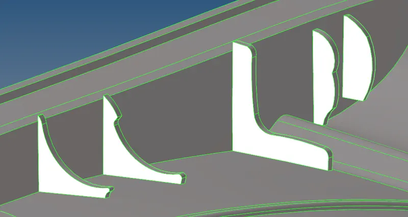
The component identified were Rib. Main A surface, Locking Ribs. etc.
1. Main A surface
2. Ribs
3. Locking Ribs
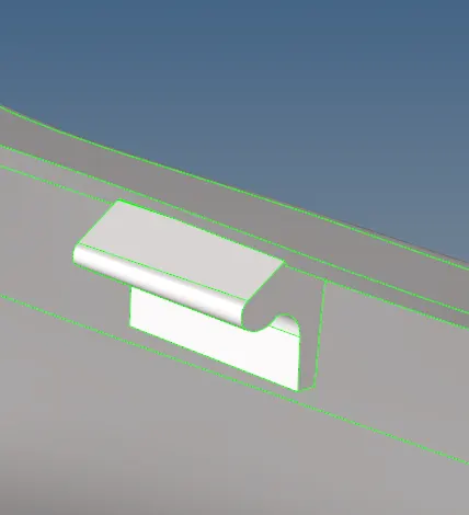
4. Door Handle Outer
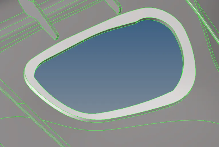
5. Dog House
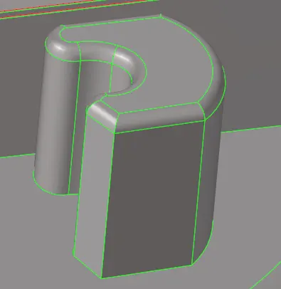
Step III - Select components one by one of the similar groups and check for the geometrical error and rectify them if any.
As we see in this model the are lot of geometrical errors in the parent geometry so we go for the next step that is mid-surface extraction by manual offset of every component.
Step IV - Extracts mid surfaces of the components using the surface edit tool offset option.
Select any one original component let's say Inner Panel A surface with measuring the thickness of the component across various sections as 2P8 mm mid-surface is extracted using offset option of extraction.

In this we select the base surface either on any side of the two surface and offset to extract the mid-surface. Manual offset help generating a proper midsurface among all the option which fit in between the original thickness of the component and gives us the mid-surface accordingly.
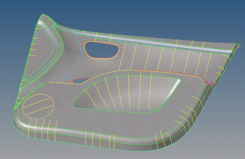
Fig - Mid Surface extraction of A surface
After Extracting the mid-surface of all the components each component mid-surface is saved as a new component with appropriate thickness identification to make it safe and confusions free from the parent geometry as shown below,
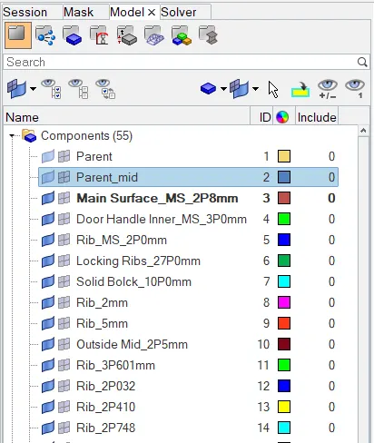
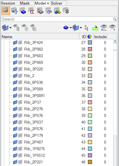
fig - Seperate Component Creation for Each
Each component with different thickness is saved seperetely to make user easily acccess the component.
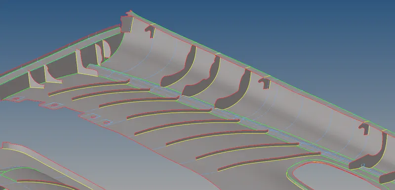
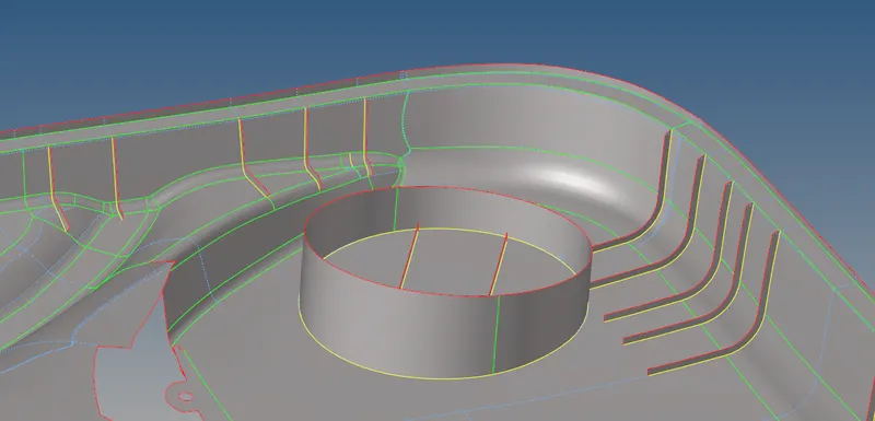
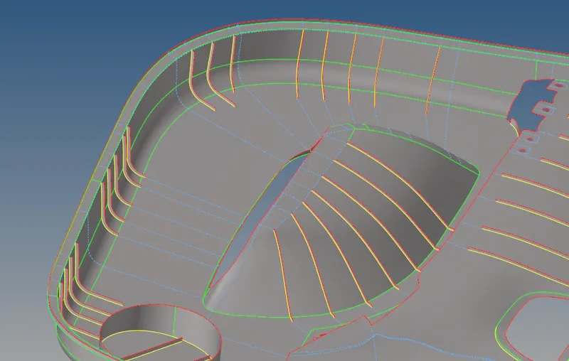
fig - Extracted Midsurface usung Offset
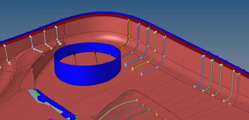
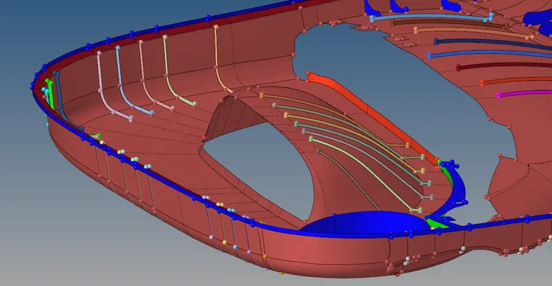
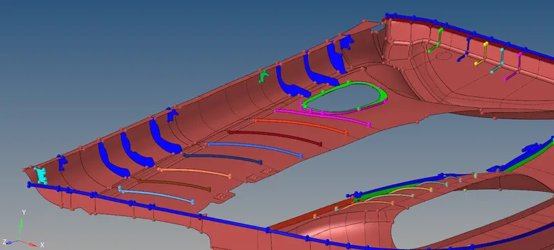
fig - Component wise Mid Surface is extracted using offset option
Step V - Checking the midsurfaces extracted properly for all the surface.
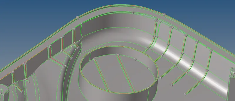
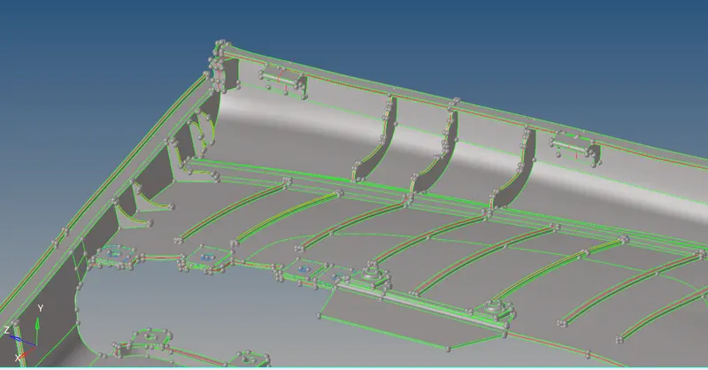
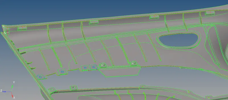
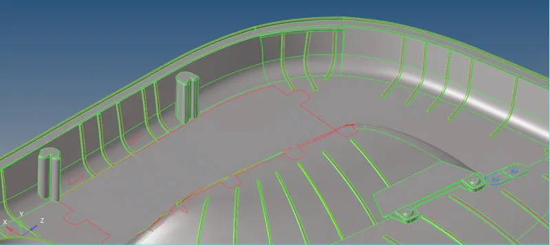
fig - Verifying the midsurface extracted properly
Step VI - Meshing the geometry (Shift + F12)
Meshing is done using the automesh option with the target length of 5mm and quality criteria are set as below to make sure that there is no element failure at the end of meshing.

Fig - Mesh Parameters
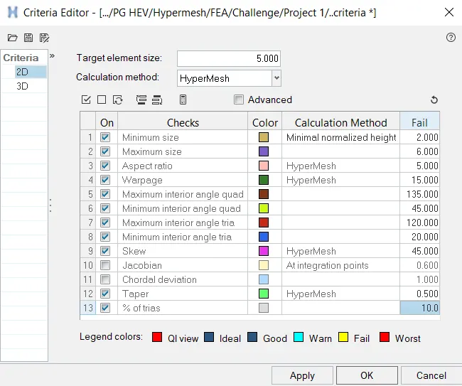
Fig - Quality Criteria
After assigning the quality criteria parameter user defeature the geometry wherever necessary keepig the important edges as it is and makes the cuts and mesh the component as below to obtain a good mesh flow of the elements.
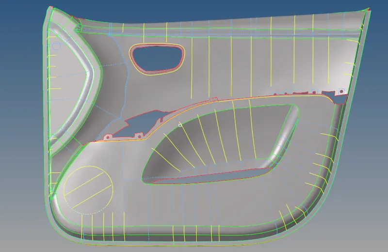
fig - Defeatured Geometry of the Door Panel
After making the defeaturing the components are meshed using automesh component in the 2D panel and with the help of various other commands like edit elements, rebuild, smooth, etc and mesh is obtained as shown below,
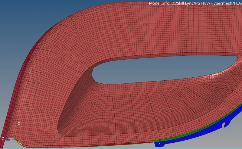
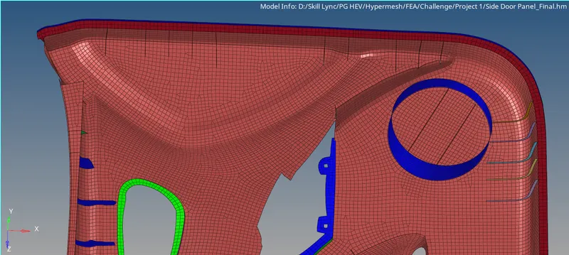
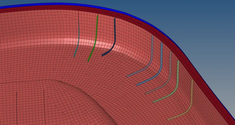
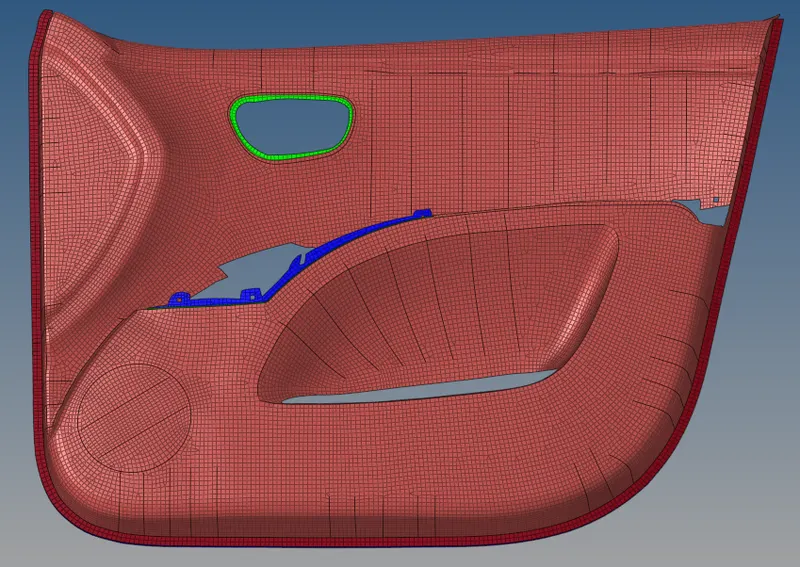
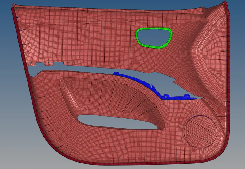
Fig - Meshed Door Inner Panel
Step VII - Quality Check
Inner Door Panel
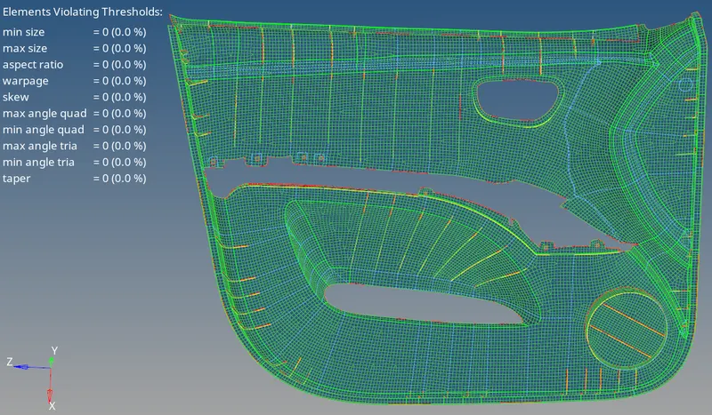
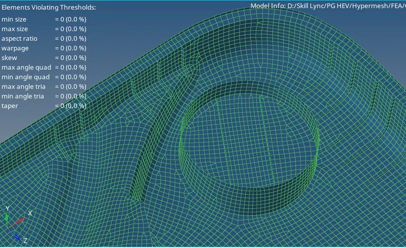
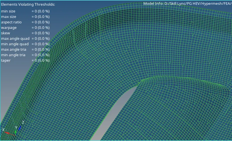
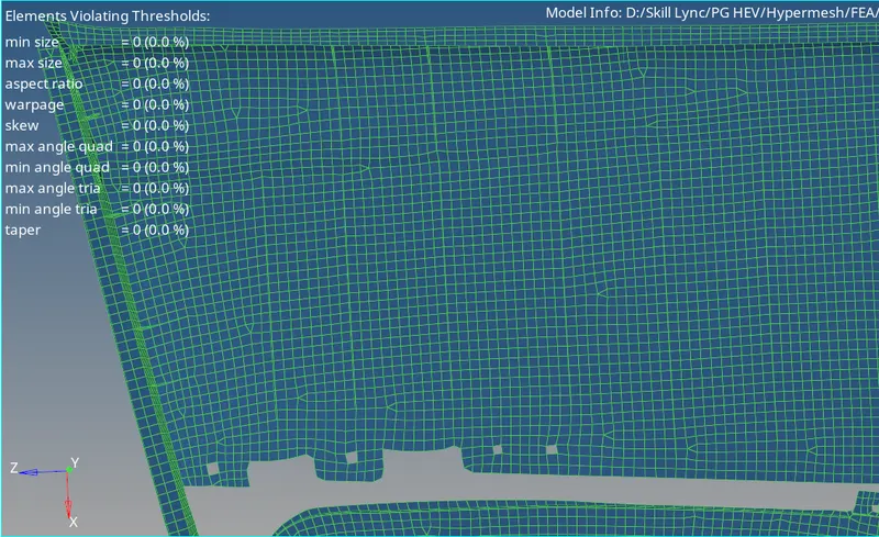
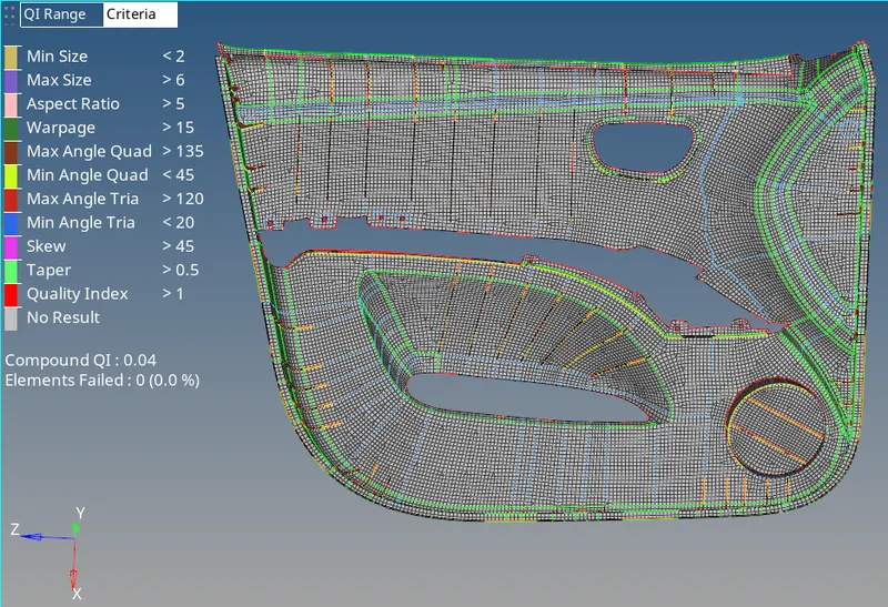
fig - Element Quality Check
There is no element failing for the set quality criteria after cleaning up all the failed elements using manual cleanup method and auto cleanup tool.
The percentage of Tria's in the ggeometry after all cleanup process is observed to be 1.9% which is within the acceptable range.

Step VIII - Free Edge Check (Shift +F3)
After checking the element quality the user check for the free edge and the equivalence of the element to ensure that that there is no gap present in the component and between the set of elements. If so that are equivalenced using the equivalence option.
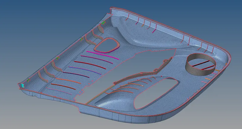
fig - Free Edge Check
Note - The color orientation is change to identify the free edge clearly in the door panel geometry.
Step X - Assign Property Card (Thickness) to the components.
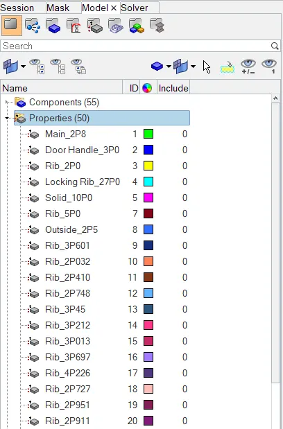
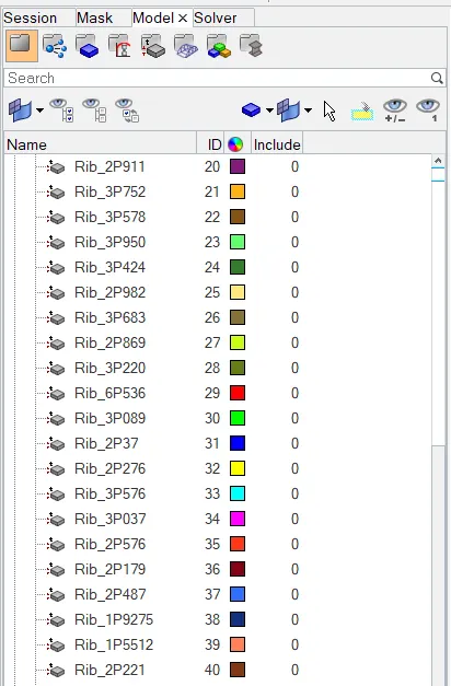
fig - Assign Property Card
After obtaining the mesh for all the components we draw the shell as solid using the 2D element representation option which can be seen in the below screenshots,
To draw the shells to solid under the visualization panel there is an option 2D detailed element representation to make the shells as solid as shown,
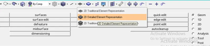
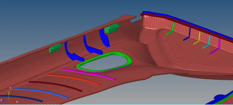
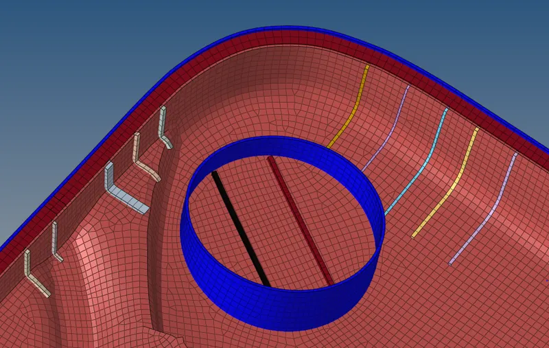
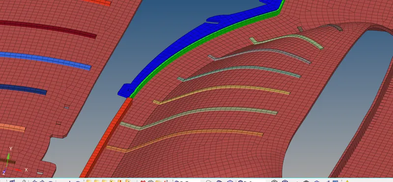
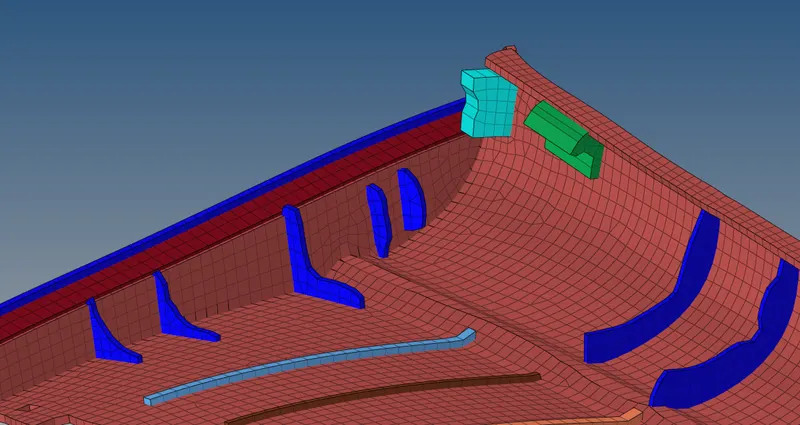
Fig - 2D Detailed Element Representation
Conclusion -
Here user can conclude that the side door inner panel is successfully meshed after the geometry topo clean up and performing all the necessary steps with the provided quality criteria. Learning outcomes are tools used to perform meshing in HYPER-MESH. There is lot of experience gained while working on this model.