2D meshing for sheet metal
2D meshing for sheet metal
AIM:
1. Take the sheet metal cad model.
2. Capture the mid surface .
3. After that mesh that mid surface and assign quality criteria .
4. Then assign thickness to that mid surface .
Procedure:
1.First we load the model in Ansa .
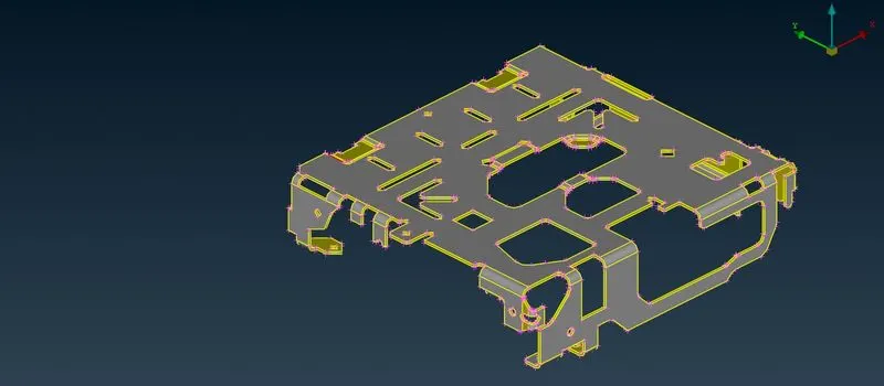
We will capture the mid surface of the geometry as we are going to do 2-D mesh and in this geometry the thickness is negligible so we are using that mid surface to get the mesh.
This geometry is a sheet metal as the thickness of the geometry is uniform throughout. If thickness varies then it is called plastic .
2. Now we are capturing cons resolution of the geometry by mesh module-perimeter - length as 1mm .
Aftar that we have to get the all planes in a single direction so go to Topo module- Faces - orient .
Then Go to Topo and check geometry and Fixing all the geometrical error by right click and auto fix we are going to create the mid surface.
3. Now we are generating the mid surface by Topo module- Faces- mid surface- skin
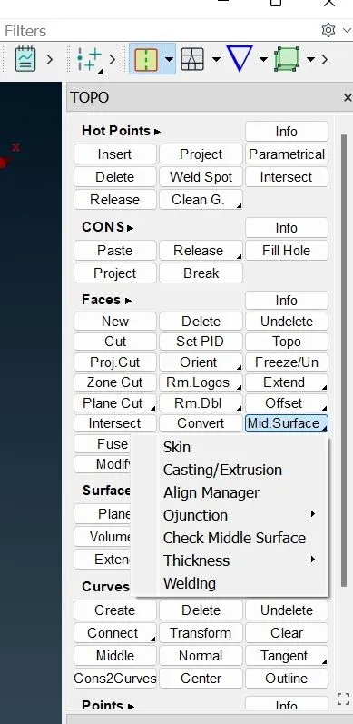
Select the geometry and middle click
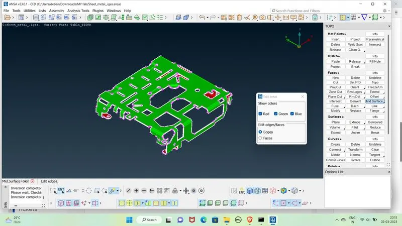
Then again middle click and then click on the face perpendicular which the mid surface would be created.
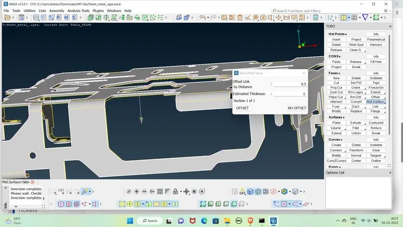
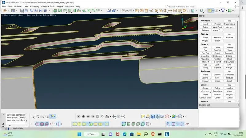
Again by offset and ok we got the above mid surface.
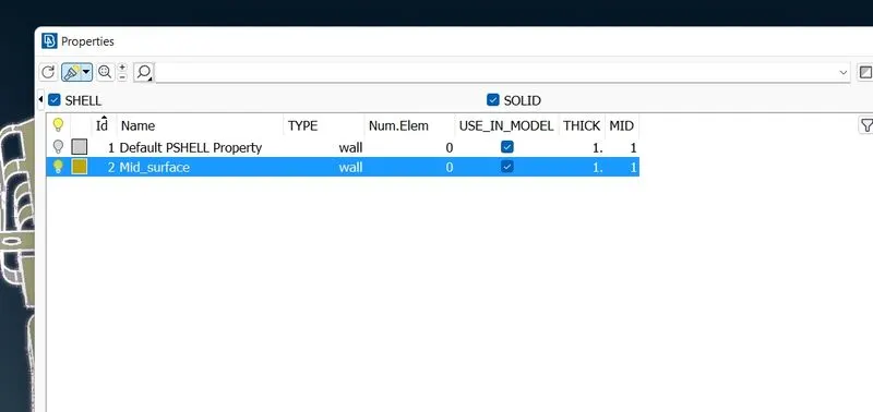
4. Now we will go to the PIDs and rename the Mid_surface by Edit option and keep it on and off the actual geometry.
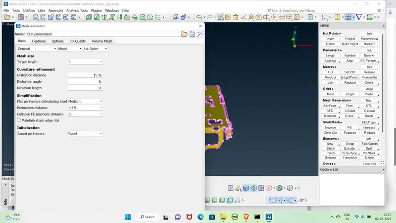
Now we are going to give the quality criteria as per given question . Before that we are going to check the mesh parameters .
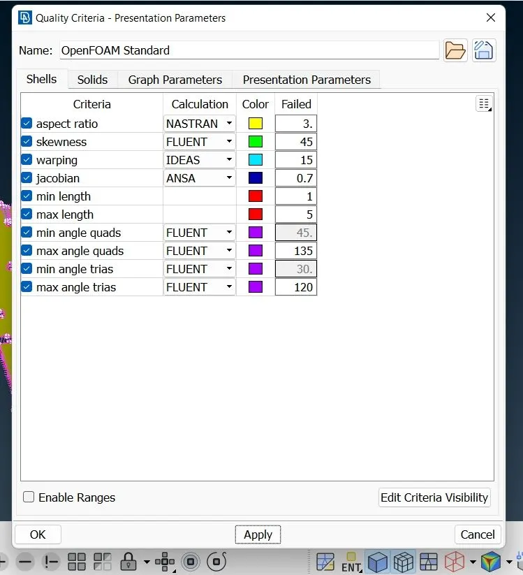
Edit quality criteria as per given above - Apply and ok .
To switch on quality criteria click on the Hidden mode .
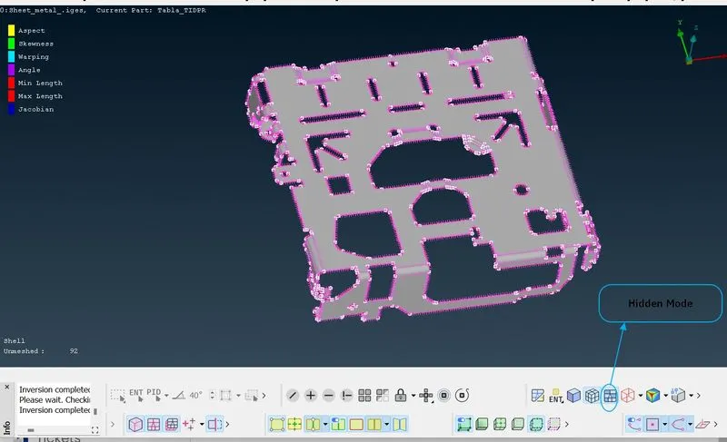
5. Now we are going to mesh the model one by one macros by mesh - mesh generation - Best mesh
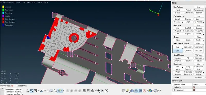
We can eliminate the off elements by - shell mesh - reconstruct / reshape / smooth .
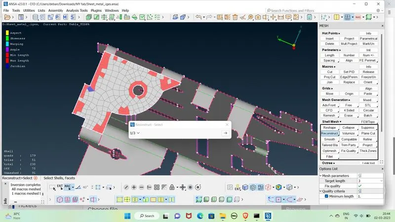
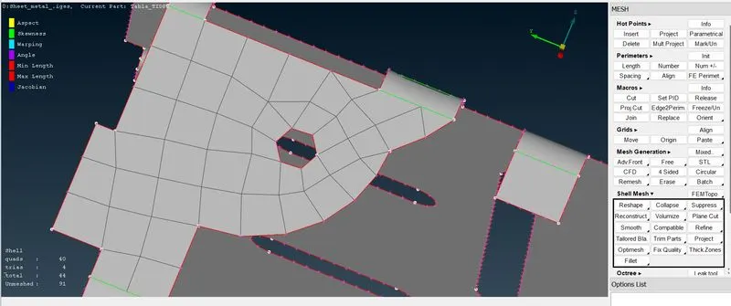
In this way we can mesh all the macroes in the geometry and we can slide the trias by Split(Forward movement) , Swap(Left/Right movement) and Paste(Backward movement ) one by one from the edges and fillets so that the trias should not create any error .
We can Join two macros by join option in macros and transform the mesh edges by edge2perim .
In this way we can mesh all the macros and remove the off elements by reconstruct / reshape / smooth option .
6. Meshed mid_surface
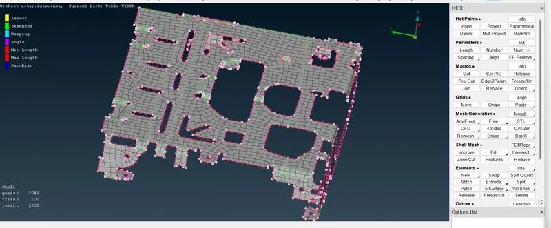
Total elements - 2250 , quads - 2048 , Trias - 202 , No off element
7. Now we are going to assign thickness to the Mid_surface
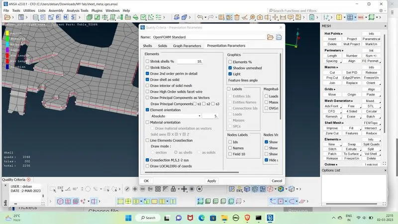
Open quality criteria - presentation parameters - check Draw shell as solid - Apply and ok .
Conclusion :
In this project we have learned that -
1. To create mesh on the surface where surface length is very greater than its thickness we are creating a mid surafce as it helps us creating 2D mesh as the 2D mesh is more convenient than 3D in terms of no of elements are less , less off elements so required computational power is also less.
2. We are avoiding trias nearer to the edges and fillets as trias have more stiffness(Force per unit length) as compared to quads so for more stressed element if it exist near the edge it can lead to break / faliure of the edge .
3. We can not remove all the trias near the edges as for quality criteria .
4. We may need to delete some hot points to make the trias into quad and increase number of edges by peremeter - Num+- to keep the quality criteria constant.
5. For crash test uniform mesh is preffered (i.e. some trias may exist) but for structural analysis no trias should exist .