23. Project 1 - Wiring Harness Routing on V16 Engine
PROJECT -1 : Wiring Harness Routing on V16 Engine
AIM
Route the Wiring harness on V16 Engine in CATA V5.
OBJECTIVES
- Define the connectors ,clips and clamps electrically for the harness bundle routing.
- Develop a Bundle Routing in V16 engine.
- Create a drawing for Routed engine assembly.
THEORY
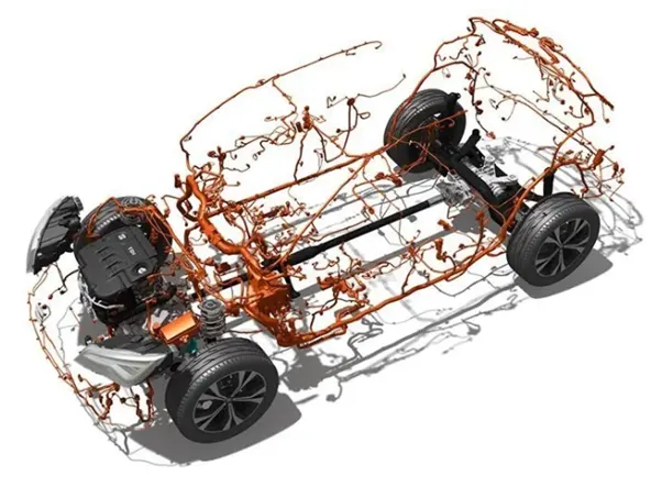
A wiring harness is a logical arrangement of wires, terminals, and connectors that runs throughout the entire vehicle and transmits data and electrical power, effectively "connecting" a number of different components. Similar to how the circulatory and central nervous systems of the human body transmit energy and information, this network does the same. Wire harnesses are collections of electrical cables used in electrical applications to carry signals. They are a collection of slack wires that have been bundled into a single covering to create a more streamlined system. Many other industries employ these wire harnesses, with the automotive industry being one of the biggest users.
For the optimum performance, automotive wire harnesses employ a wide range of wire harnesses. These harnesses integrate the electrical and electronic device wiring from several devices into a single system. As a result, they support the transfer of signals and the activation of various electrical and electronic equipment. They are made to work successfully in harsh environments and are also used to set up electrical circuits in autos.
BENEFITS OF AUTOMOTIVE WIRING HARNESS
- Reduced installation time
Consider adding numerous wires to your system. Then, think of installing a single device that connects several wires. It goes without saying that installing a single unit is far quicker than installing many units. Additionally, this lessens the possibility of faulty wiring.
- Reduced risk of shorting
The use of wire harnesses reduces the chance of electrical circuit shorts by combining many wires into rigid bundles, making them safer than loose wires.
- Great performance in harsh conditions
The materials used to make automotive wiring harnesses are strong, making the harness strong as well. These bundles are made to function remarkably well in challenging environments and to carry large power loads.
- Improved fuel efficiency
Every vehicle's ability to increase fuel efficiency is greatly helped by wiring harnesses.
- Performance in hybrid cars
Automotive wire harnesses are the ideal choices for hybrid cars since they offer exceptional performance in challenging settings as well. This indicates that these harnesses can handle electrical loads, withstand high heat, and electromagnetic noise while still transmitting large currents under challenging circumstances.
APPLICATIONS OF AUTOMOTIVE WIRING HARNESS
- Two wheelers, three wheelers, cars, utility vehicles, and commercial vehicles.
- Electrical and geometrical requirements of automobiles, and are embedded in the body, engine, and chassis of vehicles.
- Body wiring harnesses are embedded into dashboards, door locks, power windows, and interior electrical components.
- Engine wiring harnesses embed into speed sensors, lock breaking systems, cruise control systems, and fuel injection systems.
- Chassis wiring comprise of the front, rear and main harnesses.
APPLICATIONS OF AUTOMOTIVE WIRING HARNESS
- Two wheelers, three wheelers, cars, utility vehicles, and commercial vehicles.
- Electrical and geometrical requirements of automobiles, and are embedded in the body, engine, and chassis of vehicles.
- Body wiring harnesses are embedded into dashboards, door locks, power windows, and interior electrical components.
- Engine wiring harnesses embed into speed sensors, lock breaking systems, cruise control systems, and fuel injection systems.
- Chassis wiring comprise of the front, rear and main harnesses.
* Design Methodology :-
Step 1 :- download the engine CAD data and required connectors CAD data from the given source.
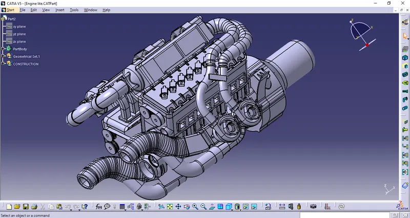
Step 2 :- Download the required Connectors from the source and convert the mechanical connectors electrically by using the electrical part design work bench by following below steps.
- First download the connectors and mounting clip from the given link source.
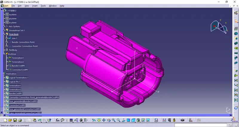
- Get into the mechanical part workbench to create required geometrical parameters. Create connector connection point and bundle connection point on the required sides of the CAD part.
- Create axis system on the connector connection point such a way that the Y coordinate facing normal to the connector face, X coordinate facing towards the locking mechanism and Z coordinate facing to the top.
- Create cavity connection point for connectors having the cavity for mounting clips
Using the geometrical parameters created,
- Define part as electrical connector.
- Define bundle connection point.
- Define connector connection point.
- Define cavity connection point.
Electrically Defined Connectors
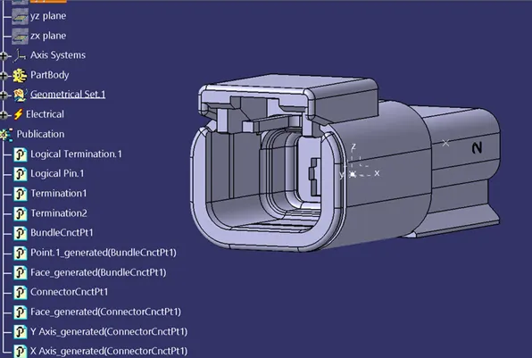
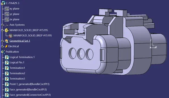
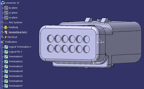
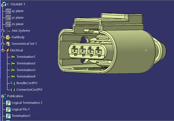
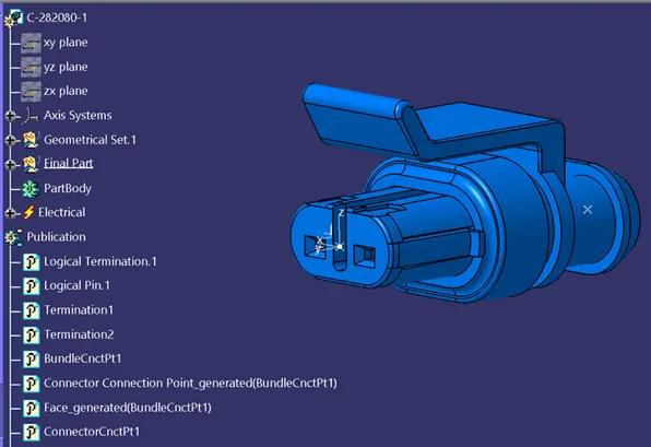
Adding Connectors to the Catalog as a Connector Family
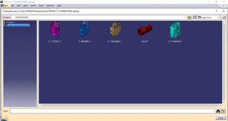
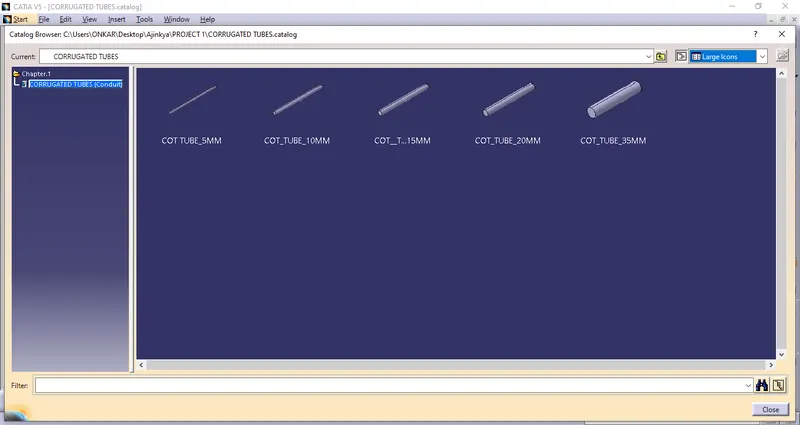
Step 3 :- Download and Define the plastic channel electrically
- Procedure for electrically defining the Channel.
- Create bundle entry point and exit point.
- Create a line curve between the main entry and exit points for creating the multi-branchable using external curve inside the channel
- Create 8 bundle entry points on the openings for connecting the injector connectors.
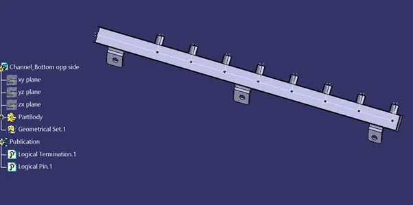
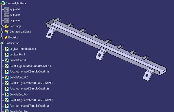
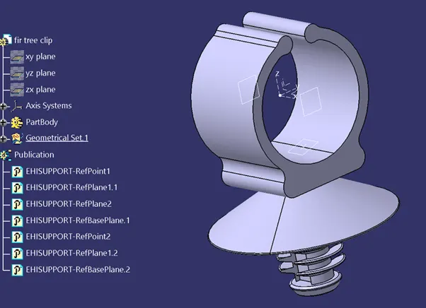
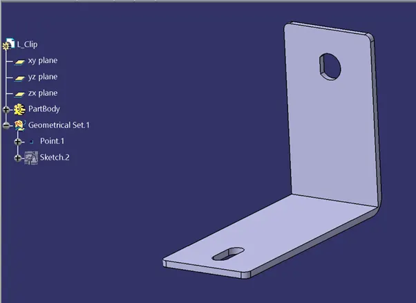
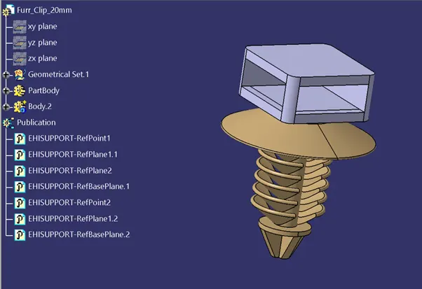
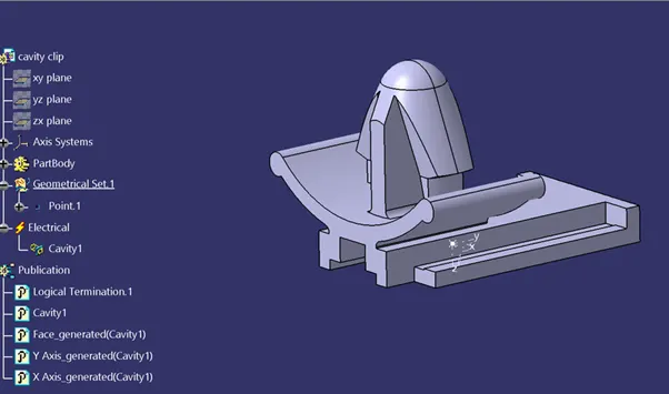
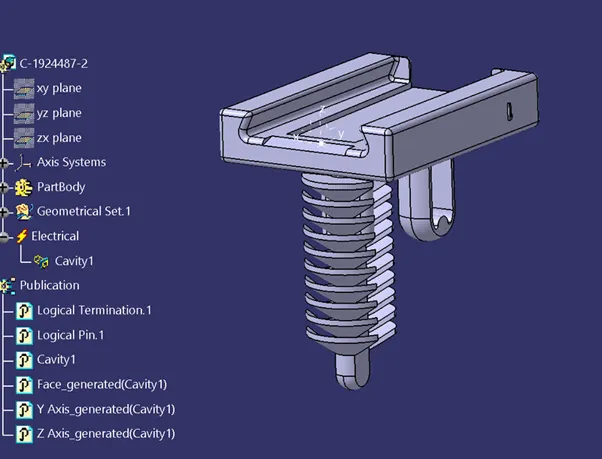
Step 4 :- download and define P-clamp, fir tree clip, L-clip and cavity clip.
Step 6 :– Creating the context assembly
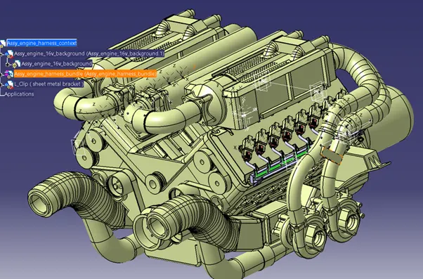
Context assembly is nothing but the product file which contains the engine 3D-CAD data and the engine harness geometrical bundle. Here the geometrical bundle product contains all the connectors and other mounting equipments, clips and clamps which are electrically defined for the assembly. Sheet metal L-clamp are added in the main context assembly.
Design criteria followed to route the wiring harness :-
- Wiring harness routed by considering the factors ease in manufacturing, accessibility, easy removal and easy maintenance of attached equipments and routing harness.
- Wiring harness should be routed in such a way that it is easy to assemble on a vehicle.
- Wiring harness should be kept away from sharp environments like sheet metal brackets, panel edges, corners etc.
- Avoid harness routing and clipping in blind zone of operator during harness during installation.
- Ensure that routing meets the clearance requirements with the different surrounding parts.
- Routing shall provide enough slack for each branch to avoid additional stress on wire and terminal crimping joints but ensure that extra slack does not cause wiring harness foul with surrounding parts and impact desired clearance requirements.
- Enough clamps should be provided to ensure the positive clearance with surrounding and safety of wiring harness.
- Use of plastic guided channels are recommended to meet the clearances in critical areas if it is difficult to achieve by use of clamps.
- Branch length should be minimum 50mm.
- Minimum distance between clip and nearest branching point should be 25mm.
- Minimum distance between two breakouts should be 50mm.
- Limit the no. of branches from single branch point upto 4.
- Ensure that harness protection is provided according to surrounding temperature, manufacturabilty and expected reliability.
- The min. bend radius is to be 1.4.
Bundle continuity :-
- In this step, first we have to make sure that multi-branchable is selected then we have to go in Edit>Search>Advanced>Workbench-Electrical>Type-Bundle Segment>Attribute-Fully Connected
- By selecting 'True' option will show all the connected bundle segments while selecting 'False' option will show all the non-connected bundle segments.
- Here, we have selected for the 'True' option and searched for results. All the bundle segments are highlighted found showing that all the bundle segments are electrically.
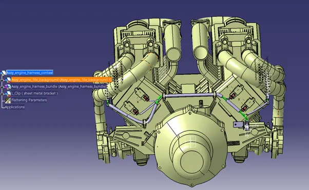
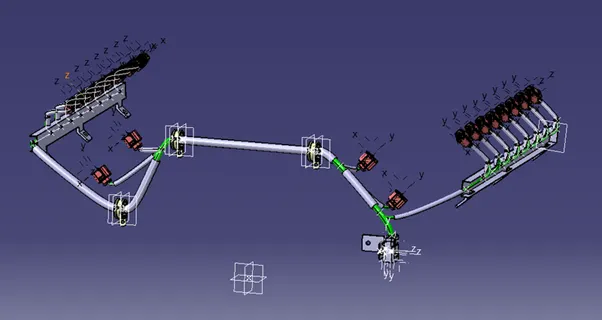

All Files are attached in a zip file below