15. DOOR LOWER TRIM WITH ENGINEERING FEATURES IN CATIA.
AIM
To create a Door Trim Lower Plastic Component through a given Class A Surface, create the Heat Stakes, Locators considering design rules and perform Draft Analysis on the final plastic component.
OBJECTIVE
- To make sure that the model meets the requirements of the draft angle.
- To create the Tooling axis using bisecting method / suitable axis.
- To perform Draft analysis on the given Class A Surface.
- To create the required Class B and Class C surfaces.
- To obtain a solid body from the surface using Close Surface feature.
- To create the Heat stakes, Locators, considering design rules.
- To perform draft analysis on final plastic component.
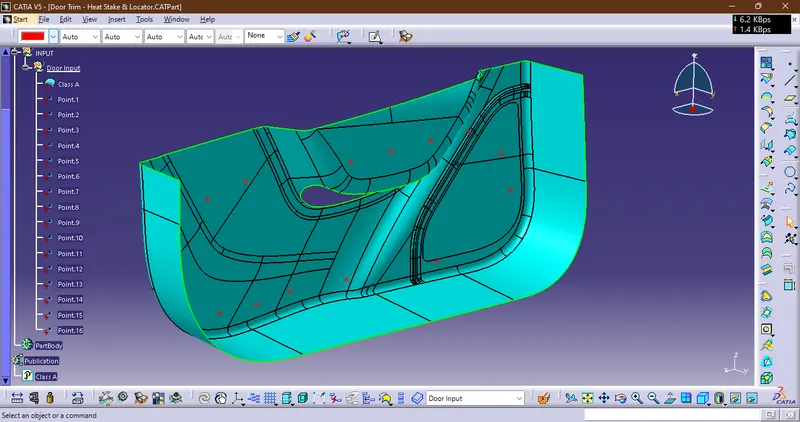
CLASS A SURFACE
- Class ‘A’ surfaces are primarily used in the automotive environment and refer to those surfaces which are visible in a product. In other words: A - class surfaces are those aesthetic/free-form surfaces, which are visible to us (interior/exterior), and have an optimal aesthetic shape and high surface quality.
- The surfaces or regions which are visible nowadays are considered for Class-A modelling. It is one of the reasons why the importance of Class-A modelling is increasing day by day. Majority of the time this term is used in Plastic Part designs.
CLASS B SURFACE
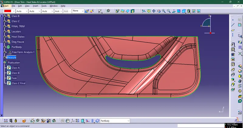
- The Class B surface is created from the Class A surface, keeping the thickness of the component in check.
- The Class B surface resembles an offsetted surface from the Class A. thickeness here we have taken as 2.5mm
CLASS C
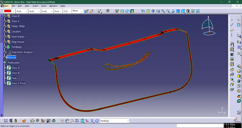
Class A is Joined with Class C to Get It Trimmed with Class B Surface So that we obtain Closed Surface Body
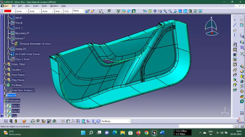
while trimming A+C, with Class B Intersections are checked to get proper trimmed
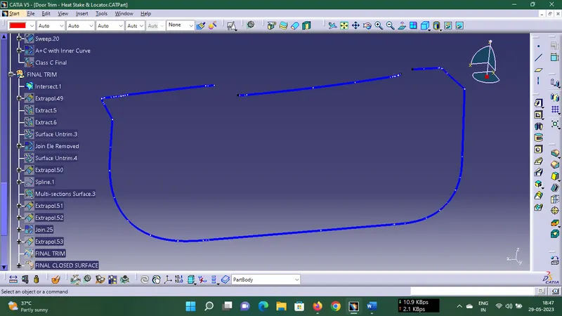
open boundry is shown here so we extrapolated areas where intersection is not proper also used multisection surface at some areas
FINAL BODY (Closed)
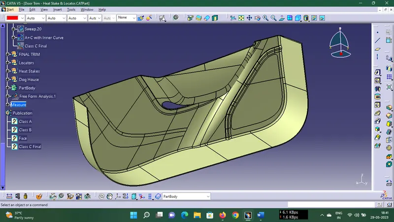
Draft Analysis of Model
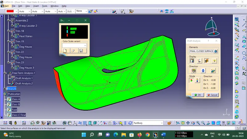
As we know minimum draft angle for the faces of the plastic component should be 3 degrees. So the value of 2.9 degrees (considering tolerance) is provided in the Draft analysis colour mode window Inside the colour scale, the GREEN bar shows the draft angle of 2.9 or above 2.9 degrees. The blue bar shows below 2.9 degrees draft angle the other limit being and the RED bar shows the negative draft angle. As shown in the image below all the top faces and side faces of the component are green, while the bottom faces are red. The line of demarcation between the green and red faces is the parting line which divides the core and cavity halves. The solid model has cleared the draft analysis successfully as shown in the image below.
Creation of 4 Way Locators and Heat stakes
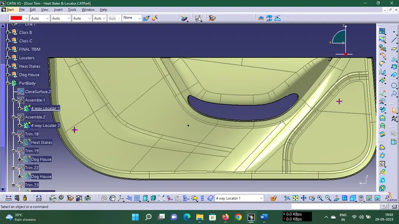
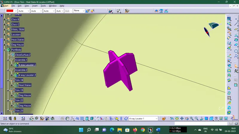
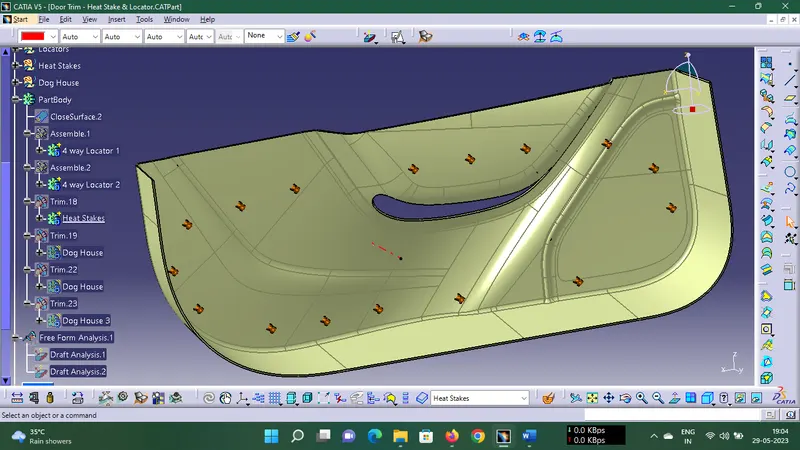
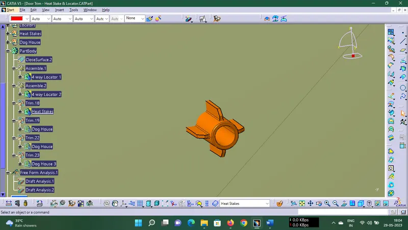
The Orange colored cylinders are the heat stakes.
These heat stakes will enter the mating component and using a heat staking machine these heat stakes are melted and cooled. When cooled this will get hardened and the two components will stick together. Thus all degrees of freedom are arrested.
while creating heat stakes and ribs onle first soild is created after power copy tool is used and while pasting
special paste as a result with link is used to create link as parent child it is more easier.
FINAL MODEL and Dog Houses
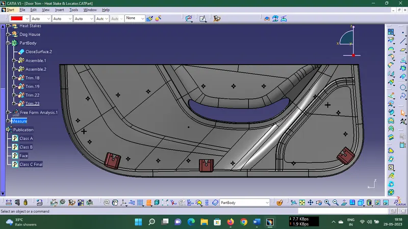
CATPart File Is attached Below