1. Development of a Door Trim panel.
Development of a Door Trim panel :-
AIM :-
To create a CAD model of solid body on the back left side door of a vehicle considering following inputs like using CATIA V5 tool using the given Class A surface and master section and adding thickness to the component.
A) Nominal thickness : Refer master sections
B) Attachment strategy : Find the attachment strategy for the door panel complete work.Use Push pin with Dog house for Lower substrate – Door panel attachment Use heat stakes for part to part attachment.
SOFTWARE USED :
CATIA V5-R20
INTRODUCTION :-
SIDE DOOR PLASTIC TRIM :-
An interior plastic component attached to the inner side of the door. This product improves the appearance of the vehicle intertior and also creates a more comfortable interior by providing a variety of fitments and functions.
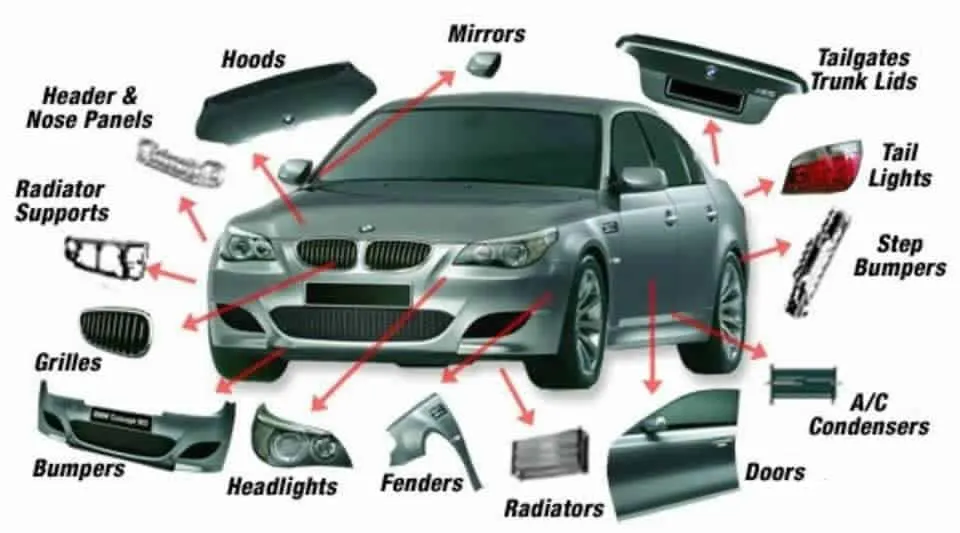
SOME OF THE PLASTICS USED IN A CAR ALONG WITH AREA WHERE IT IS USED IS SHOWN BELOW :-
INJECTION MOULDING :-
Plastic parts are all individually designed and manufactured by a method called injection moulding .
Plastic injection molding, or commonly referred to as injection molding, is a manufacturing process used in the mass fabrication of plastic parts.
It involves an injection of molten plastic material into the mold where it cools and solidifies to its final form.
It is ideal for manufacturing high volumes of plastic products, which serves many industries and individuals.
PROCEDURE :-
1.Surface classes :-
all plastic parts are made by number of surfaces.while proper understanding while designing the plastic parts.
all surfaces are classified into three groups there are
1) A-surface
2) B- surafce
3) C-surfaces
1.1 A- class surface :-
how it look/visible the product in our view tells us the class -A.
Following points are related to A-Surfaces :-
1. To design the outer visible surface of part
2. Design in this way to maintain aesthetic look of parts .
3. A- surface may have texture
4. A - suraface gave curvature continuity
5. A-surface don't have any ribs,bosses ,snap or gussets.
The first step to follow in this project is to extract the CLASS-A surface (individually for each component) of the Door Trim Panel and divide these surfaces into different Geometrical sets as follows :-
1.Door arm retst
2.Lower Substrate
3.Upper Substrate
4.Bottle handle
1.1.DOOR ARM REST CLASS A SURFACE
1.2.LOWER SUBSTRATE CLASS A SURFACE
1.3.UPPER SUBSTRATE CLASS A SURFACE
1.4.BOTTLE HANDLE CLASS A SURFACE
OVERALL CLASSS A SURACES :-
2.CREATING THE POINT :-
Here the point gives the direction of tooling axis.
2.1 CREATING THE POINT IN ALL 4 THE COMPONENTS :-
3.TOOLING AXIS CREATION :-
Tooling axis plays important role in plastic product manufacturing and designing, this axis decides the direction in which mould is going to work while production of the component.
FIG 1.TOOLING AXIS
3.1 CREATING THE TOOLING AXIS IN ALL 4 THE COMPONENTS :-
4.CHECKING DRAFT ANALYSIS OF CLASS A IN ALL THE 4 COMPONENTS :-
DRAFT ANALYSIS-
- Final plastic parts are the nominal draft angle is 3 degrees but even 7degree is allowed for the subassemblies like ribs and slots.
- Insert< Analysis< Feature draft analysis
- First the compass is moved to the part which used to define the tooling axis new current draft direction then lock the draft direction using the lock icon.
- The color of the chart indicates the draft if the color is indicated that means the part passes and used for further operation.
- By using the analysis under the running point icon, we can check draft angle at the various surface of the component.
- If the surface satisfied the draft angle, then it shows the green color if not appears in red color.
4.CHECKING DRAFT ANALYSIS OF CLASS A IN ALL THE 4 COMPONENTS :-
5) B CLASS SURFACE :-
B- surface is invisible to viewer
FOLLOWING POINT RELATED TO B -SURFACE :-
1.To design the inner invisible surface of part
2.design in the way to maintain volume of inner hollow portion
3.B-surface have tangent continuity
4.B-surface don't have texture
5.B-surfaces need to be created according to A- surfaces
[NOTE :- THE BELOW GREEN COATED SURFACE IS THE CLASS B SURFACE OF THE THE 4 COMPONENTS]
5.1CREATING THE B SURFACE USING MASTER SECTION IN ALL THE COMPONENTS :-
5.2 CREATING THE DOOR ARM REST OF CLASS B SURFACE
5.2 CREATING THE LOWER SUBSTRATE OF CLASS B SURFACE
5.2 CREATING THE UPPER SUBSTRATE CLASS B SURFACE
5.2 CREATING THE BOTTLE HANDLE OF CLASS B SURFACE
OVERALL CLASSES B SURFACES :-
6) C CLASS SURFACE :-
C -Class surfaces are created to class A & B
FOLLOWING POINT RELATED TO C - SURFACE :-
1. C- class surface are created to close A ,B & C
2. C - Surfaces don't have texture
3. C -surface don't need any type of tangent continuity
4. it is using engineering patches or using reference of environmental parts
[NOTE :- THE BELOW RED COATED SURFACE IS THE CLASS B SURFACE OF THE THE 4 COMPONENTS]
6.1. CREATING THE DOOR ARM REST OF CLASS C SURFACE :-
6.1 CREATING THE LOWER SUBSTRATE OF CLASS C SURFACE
6.1. CREATING THE UPPER SUBSTRATE OF CLASS C SURFACE :-
6.4 CREATING THE BOTTLE HANDLE OF CLASS C SURFACE
6.5 CREATION OF CLOSED SURFACE
- join the class A and class c surface and named it as AC
- join the AC surface to the B surface
- by joining them the closed surface will get
- The join of Class A and Class C surface is trimmed with class B surface to create a closed surface. While performing trim operation errors were coming as a proper intersection was not happening.
- Hence with the help of extrapolating command class B surface was extrapolated and finally trimmed.
7.ADD ALL THE A+B+C SUFACES :-
7.1. CREATING THE DOOR ARM REST OF CLASS A+B+C SURFACE :-
7.2 CREATING THE LOWER SUBSTRATE OF CLASS A+B+C SURFACE :-
7.3. CREATING THE UPPER SUBSTRATE OF CLASS A+B+C SURFACE :-
7.4 CREATING THE BOTTLE HANDLE OF CLASS A+B+C SURFACE
8.CREATING THE MAIN BODY OF ALL THE 4 COMPONENTS :-
9.DRAFT ANALYSIS OF THE MAIN BODY OF ALL THE 4 COMPONENTS :-
10. DOG HOUSE :
Dog house is an engineering feature used in plastic trim design. Dog houses are used as supporting feature. Sometimes other engineering features like snaps; locators etc. are mouted on them to increase their strength.
Dog houses are subjected to draft analysis to prevent breakage of the component during ejection from mould cavity.
Dog house and other engineering components are built on B-surface.now we will proceed with creating a dog house and mount the boss on it by following the design rules mentioned below :
DOG HOUSE DESIGN PROCEDURE ( SAMPLE REFERENCE) :-
10. DRAFT ANALYSIS AFTER CREATING THE DOG HOUE AND HEAT STAKE MAIN BODY OF ALL THE 4 COMPONENTS :-
11.PUSH PINS
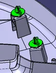
- push pins are used to join one component to other in here push pins are inserted or attached to dog house
- the dimesions are taken from the below shown figure reference
12.HEAT STAKE
- heat stake is permenant joint techninque .in here heat stake is used to join the two plastic components
- Heat staking also known as thermoplastic staking is the process of joining two dissimilar materials together.
- In heat staking we use local heating and cooling to raise the temperature of plastic components and allow plastic reforming to be carried out.
- This reforming can be used in a wide variety of applications.
13.RIB
- RIB IS A BLENDED FEATURE ON Parts in order to provide strength of the wall .
- the ribs are created on lower substrate
- Ribs are thin, wall-like features typically designed into the geometry of a part to add internal support to walls or other features like bosses. In a similar fashion, gussets are support features that reinforce areas such as walls or bosses to the floor.
11.DRAFT ANALYSIS OF THE ALL THE 4 COMPONENTS :-
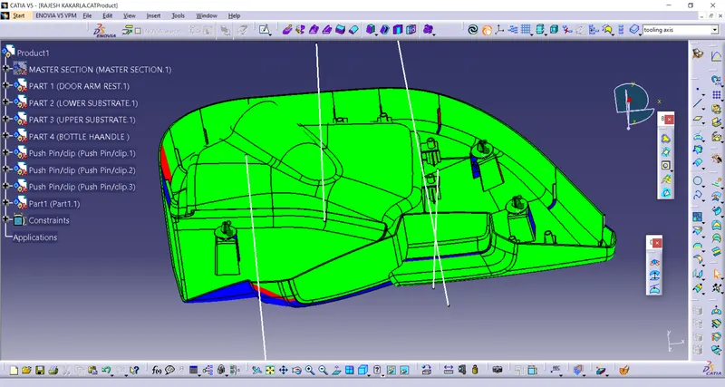
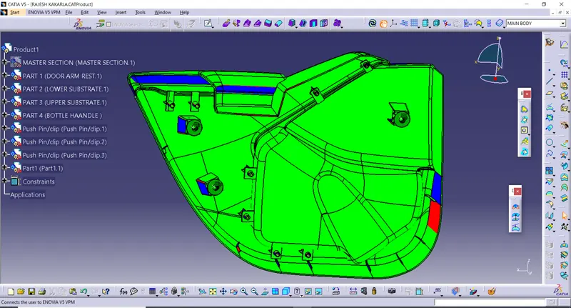
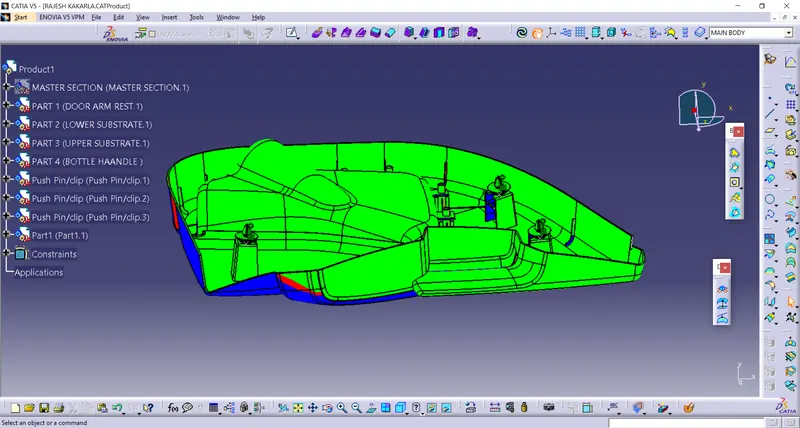
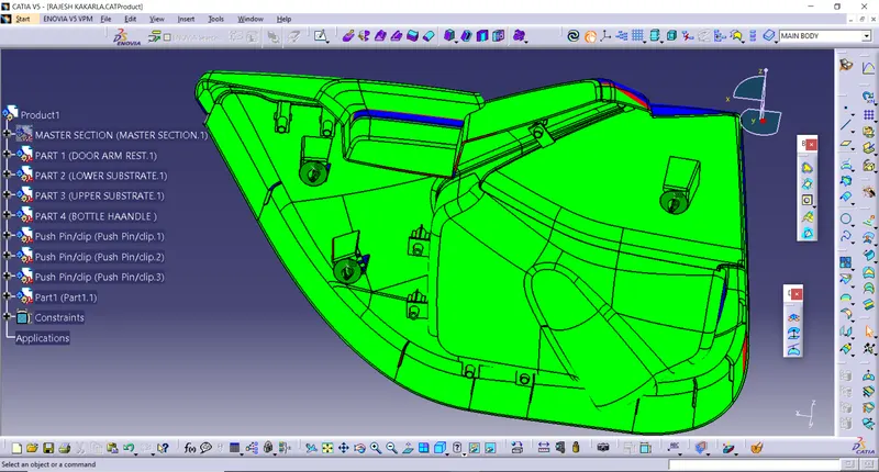
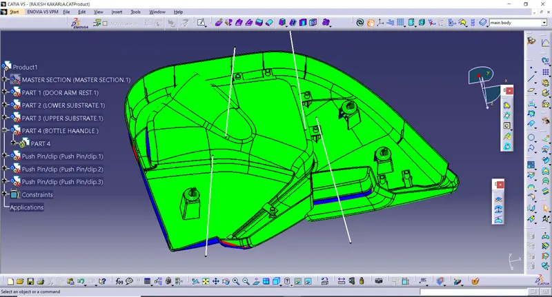
TREE STRUCTURE FOR ASSEMBLY OF DOOR TRIM PANEL :-
CONCLUSION :-
The door panel successfully designed by following all design rules used in automotive industry. all attachment strategy for the door panel complete work,Use Push pin with Dog house for Lower substrate – Door panel attachment use heat stakes for part was attached.
[NOTE :- IN CASE IF THE FILES ARE NOT OPENED,PLEASE KINDLY CONTACT ME -8074048108 [0R] [email protected] ]