Electrical · PG program

Post Graduate Program inPower Converter Design and Analysis

This 12 month program from Skill-Lync equips the student with the necessary knowledge required to perform the design and analysis of power converters used in electric and hybrid electric vehicles.

Duration
48 weeks
Content
99 hours
Courses
6
Projects
12
Mode
Online
Overview

What you'll
be able to do.

  • A thorough understanding of Power Converters, Simulink, Matlab, and PCB Design
  • Detailed understanding of Stateflow for Control Logic
  • Knowledge of Rectifiers and Converters
  • Understanding of Altium software tools for PCB design
  • Complete understanding of DC-DC converters, Control Theory, and Modeling of Closed Loop Buck Converter
  • Hands-on experience in using various software which aids in design and simulation

Why this program

  • The students will have a thorough knowledge of Power Converter Design and Analysis.
  • They can specialize in the domain and gain complete in-depth knowledge of it.
  • The students are exposed to the modern trends & the standard practices followed in the industry right now.
  • After completing this course, students will get detailed knowledge and design insights of power electronic converters.
  • With this knowledge, students will be able to design, simulate and analyze the converters.
  • The details of rectifier circuits covered in this course will be helpful to tackle the challenges in power electronic industries and would be useful for building industrial/commercial products.
  • Higher Education
    • Power Electronics and Drives
    • Power Systems
    • Electrical Machines
    • Control and Instrumentation
    • Applied Electronics
  • Job Opportunities
    • Power Electronics Engineer
    • System Modeling and Simulation Engineer
    • Hardware Design Engineer
    • PCB Design Engineer
Tools you'll use
SimulinkMATLABAltium DesignerLTspice
Curriculum

6 courses,
64 modules.

Get the full syllabus ↓
  1. 01Introduction to Physical Modeling using Simscape4 modules
    1. Introduction to the Modeling of Complex SystemsW01

      As complex systems have numerous parts interacting with each other, they are difficult to model. Mathematical models can be used to model these complex systems, and provide an understanding of how they function. By using Simscape, engineers can develop physical models, model control systems, and test performance at the system level. It is important for learners to understand complex system modeling using Simulink, and physical system modeling using Simscape.

      This week will cover

      • Importance of mathematical modeling
      • Block diagram approach & model-based design for engineering systems
      • Basics of the Simulink environment
      • Creating a simple model
      • Obtaining results
      • Basics of various Simulink toolboxes

    2. Simulation Configuration and SimscapeW02

      Simscape is used to develop models that represent physical systems in the Simulink environment. It also lets users assess system-level performance. When setting up a model for simulation on Simulink, there are specific configurations to be followed. It is important for learners to understand how to model and configure simulations using Simscape.

      This week will cover

      • How models run in Simulink
      • Types of solvers
      • Model configuration
      • Continuous & discrete-time systems
      • Timestep
      • Solving ordinary differential equations (ODEs)
      • Physical modeling using Simscape
    3. Simulink with Script and WorkspaceW03

      Simulink and MATLAB are closely integrated as Simulink models can be developed, solved, and interacted with by using MATLAB scripts. These script files have a series of statements with commands and functions that can be carried out at runtime. Simulink models can also access the MATLAB Base Workspace and Model Workspace to identify required parameters. It is important for learners to understand how MATLAB and Simulink are interfaced.

      This week will cover

      • Using a script file with Simulink models
      • Creating a subsystem
      • Variant subsystem
      • Projects
      • Template
      • Lookup tables
      • Running simulation in steps
    4. Stateflow for Control LogicW04

      Stateflow is used to elaborate on how MATLAB and Simulink respond to events, time-based variables, and input signals. It is a graphical programming platform based on finite state machines that can be used by engineers to design control logic. It is important for learners to understand the use of Stateflow in engineering applications.

      This week will cover

      • Control logic for engineering applications
      • Using a finite state machine
      • Making logic diagrams
  2. 02Simulation and Design of Power Converters for EV using MATLAB and Simulink12 modules
    1. Introduction to Switched Mode Power Converters, Performance and Analysis of Buck DC/DC ConverterW01

      The following concepts are discussed in this week:

      • A brief introduction on the need of switch mode power converters and their everyday applications.
      • The performance and analysis of buck DC-DC converters.
    2. Simulation of Boost DC/DC ConverterW02

      The following concepts are discussed in this week:

      • Simulation tools from different software packages are covered
      • The studied tools are used to simulate and perform high-level design of a boost DC-DC converter
    3. Boost DC/DC Converter, Gate Driver DesignW03

      The following concepts are discussed in this week:

      • The performance and analysis of boost DC-DC converters.
      • Using simulation tools from different software packages to simulate and perform high-level and gate driver design of a boost converter.
    4. UP/Down DC/DC ConvertersW04

      The following concepts are discussed in this week:

      • The performance and analysis of various UP/Down DC-DC converters.
      • Implement design techniques using simulation tools on the studied Up/Down converters.
    5. Discontinuous Conduction ModeW05

      In this week, the following operations are done for DC-DC converters operating in discontinuous conduction mode (DCM).

      • Performance
      • Analysis
      • Simulation
    6. Modeling of DC-DC ConvertersW06

      The following concepts are discussed in this week:

      • The development of small signal models for various DC-DC converters.
      • Build simulation blocks to validate the modeled systems.
    7. Feedback Control of DC-DC ConvertersW07

      The following concepts are discussed in this week:

      • The design of feedback control system using analog circuits for DC-DC converters.
      • Simulate a fully designed closed loop DC-DC converter.
    8. Isolated DC-DC convertersW08

      The following concepts are discussed in this week:

      • The performance, analysis, and simulation of various isolated DC-DC converters.
      • AC-DC rectifiers performance and simulations
    9. AC-DC rectifiers performance and simulationsW09

      In this week, the following topics related to AC-DC rectifiers are discussed:

      • Performance
      • Analysis
      • Simulation
    10. DC-AC Inverters Performance and simulationsW10

      In this week the following topcis related to DC-AC inverters are discussed:

      • Performance
      • Analysis
      • Simulation
    11. AC-DC Rectifiers Design, DC-AC Inverters Design W11

      In this week, the following about inverters and rectifiers are discussed:

      • Design
      • Analysis
      • Applications
    12. Modern Applications of Power Electronic ConvertersW12

      The following concepts are discussed in this week:

      • Modern applications of power electronic converters in electric vehicles
      • Renewable energy systems
      • Data centers
  3. 03Design Concepts of Power Electronic Converters for Industries12 modules
    1. Power Electronics and their Industrial ApplicationsW01

      In this module, the students will learn about the basics of power electronics, different types of power converters that are used in industry, and their applications. The topics include

      • Basics of Power Electronics
      • Types of Power Converters and their Applications – DC/DC, AC/DC, DC/AC, and AC/AC Converters
    2. Power Converter Components and Design StandardsW02

      The successful design of Power converters requires efficient component selection. Another major part of the design is meeting the different Industry standards. In this module, the students will learn about different power electronic components and an overview of the industry standards.

      • Introduction to Power Components
      • Industry Standards
    3. Power Switching DevicesW03

      The heart of every power converter is a switching device, and in this module, the students will learn which devices are used in different topologies, and why?

      • Types of Power Switching Devices – MOSFETs, IGBT, SCR, and Thyristor
      • Selection of Switching Device based on Application
      • IGBT and MOSFET Datasheet Overview and Analysis
    4. Wide Band Gap DevicesW04

      With the evolution of semiconductor technology, wide bandgap devices are now popular with the benefits of higher switching frequency, reducing the overall size of the power converter. In this module, the students will learn the following topics

      • Introduction to Wide Band Gap Devices
      • SiC and GaN MOSFETs Overview
      • Design and Processing of WBG Power Devices
      • Selection of WBG Devices
    5. Switching Methods for Power Electronics DevicesW05

      In this module, the students will learn how to operate a DC/DC converter or DC/AC converter with different switching methods and understand their pros and cons. The topics include

      • Different Switching Methods and Theory
      • Deep Dive into Sinusoidal PWM and Space Vector PWM Strategy
    6. Controls Theory and Modeling of Closed Loop Buck ConverterW06

      Modeling a power electronics converter in real-world application requires regulation of output voltage/current. In this module, the students will learn the basics of control systems and transfer function derivation. Also, they will learn about Buck Converter Design and analyze the transfer function. The topics include

      • Basics of Control Systems
      • Laplace Transforms
      • Derivation of Transfer Function
      • Transfer Function Analysis of Buck Converter
    7. Introduction to MagneticsW07

      Magnetic design is crucial in any power supply, DC-DC converter applications, gate driver design. In this module, the students will investigate the different concepts of magnetic design and design a push-pull transformer. The topics include

      • Basics of Magnetic Design
      • Inductor Design
      • Design of Gate Driver Transformer
    8. Power Electronic TopologiesW08

      The first step in implementing any power converter is to determine which topology suits the desired application. In this module, the students will learn different inverter topologies that are used in the industry. The topic include

      • Single-level Inverter
      • Multi-level Inverter
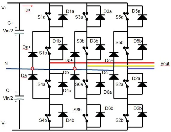
      • Neutral point Clamped Inverter
      • Matrix Converter
      • Cyclo Converter
    9. Single Phase InvertersW09

      Inverters are one of the most essential power conversion devices, that can be found on UPS, TV, Electric Vehicles, Substations, etc. In this module, the students will understand the basics of inverter and single-phase inverter design. The topics include

      • Basics of Inverter
      • Single-phase and Three-phase Inverters
      • Modeling of 3 Phase Inverter
    10. Introduction to Electric DrivesW10
    11. Cooling System DesignW11

      In this module, the students will learn about the types of heat losses in power electronics devices, how to model them, and design an efficient cooling system. The topics include

      • Switching and Conduction Losses
      • Understanding the Power Losses from the IGBT Datasheet
      • Calculation of Power Loss for Three-phase Inverter
      • Deriving Efficiency of a Three-phase Inverter
      • Design and Selection of Cooling System
    12. Snubbers & DC link CapacitorW12

      While designing any high-frequency power converter, the major challenge that a designer faces is on suppressing the switching transients on the switching devices. Since most of the failures on switching devices are because of high voltage transients. In this last module, the students will learn about the Snubbers, their applications, and their design. The topics include

      • Theory of Snubbers
      • Types of Snubber Topologies
      • Calculation of Snubber Parameters
      • DC Link Capacitors
  4. 04Advanced PCB Design Using Altium12 modules
    1. Introduction to Altium PCB DesignW01
      • Introduction to Altium ECAD software
      • Project Template
      • Library Files
      • Schematic Sheet
      • Layout
      • Fiducials and Mounting Holes
      • PCB Design Concepts
      • PCB Grid Settings
      • PCB Revision Control
    2. Understanding DatasheetW02
      • What is a Datasheet?
      • How to Identify Parts in a Datasheet?
      • How to IDentify the Key Points in a Datasheet Related to PCB Design?
      • Manufacturer Part Number
      • Package Type
      • Pinout Description
      • Footprint
      • PCB Routing Techniques
      • CAD Information
    3. Creating Schematic SymbolsW03
      • What is a Schematic Symbol?
      • Create Schematic Symbols from Scratch
      • Adding Designators, Descriptions, and Attributes
      • Adding Schematic Nets
      • Placing Component in Schematic
      • Finalizing the Schematic
    4. Creating PCB footprintW04
      • What is a Footprint?
      • How to Create a Footprint?
      • What are Altium Layers?
      • What are PCB Components?
      • How to Import a Component from Altium Vault?
      • What is a Board Outline?
      • What is Via Definition?
    5. PCB LayoutW05
      • Setting Clearance Rule
      • Layer Stack-up
      • Importing Components into a Layout
      • Component Placement
      • PCB Variant
      • PCB Routing Definition
      • PCB Routing Topology
    6. Adding Polygon Pour and Thermal ReliefW06
      • Polygon Pour
      • Thermal Relief
      • Stitching Via
      • Via Shielding
      • Keepout
      • Adding Text
      • DRC Check
    7. EMC EMI ConsiderationW07
      • EMC & EMI Definition
      • PCB Copper Plane
      • PCB Traces
      • Faraday's Cage
    8. PCB Design using Saturn PCB ToolW08
      • Saturn PCB Design tool
      • Via Properties
      • Conductor Properties
      • Differential Pair
      • Crosstalk Calculator
    9. High Speed Design RoutingW09
      • Signal Integrity
      • High-speed Design Definition
      • Stack-up for High-speed Design
      • Accordion
      • Impedance Matching
      • Differential Pair Routing
      • Crosstalk Definition
      • Eliminating Crosstalk
    10. Double Sided PCBW10
      • Single Side Vs Double Side PCB
      • Double Side PCB Advantages
      • Double Side PCB Disadvantages
      • Fan Out Concept
      • BGA Component Fan Out
    11. PCB Panelization and Generating Gerber DataW11
      • PCB Panelization
      • Gerber Definition
      • Generating Gerber Data
    12. Output File GenerationW12
      • Generate 3D View
      • Generate BOM
      • Generate X Y Data
      • Altium Draftsman
      • Generate Output Data
  5. 05AC-DC Rectifiers, Harmonics and Related Standards12 modules
    1. Overview of Power Electronic DevicesW01
      • Importance of AC-DC converter in any power electronic converter application
      • Advantages of AC-DC converters
      • Applications of AC-DC converters in residential and industrial applications
      • Introduction to device characteristics of Diode
      • Thyristor, MOSFET and IGBT (Only relevant details to this course will be covered)
      • Introduction to state of the art wide-bandgap devices (SiC and GaN)
      • Criterion of device selection.
    2. Introduction to Simulation Tools and Classification of AC-DC ConvertersW02
      • Introduction to simulation platforms of MATLAB and LTspice
      • Basic details of simulating any general circuit in MATLAB and LTspice
      • Device installation in LTspice
      • Usefulness of these software tools for different scenarios
      • Detailed classification of AC-DC converters
      • Examples of these converters with their circuit diagrams (Half wave, full wave, boost rectifier, PWM rectifiers, etc.)
      • Applications of these circuits for different scenarios
    3. Uncontrolled AC-DC Converters: Diode Based Circuits and Simulations (Single-Phase)W03
      • HWR operation with R, RL, RLE and RC loads
      • Simulations and analysis
      • FWR operation with R, RL and RC loads
      • Effect of source inductance and process of commutation
      • Simulations and analysis
      • Power computations
      • Power quality parameter computations and study of harmonic issues
    4. Three-Phase Uncontrolled AC-DC Converters W04
      • HWR operation with R loads and analysing the effect of transformer on operation
      • Simulations and analysis
      • Operation of full-bridge three-phase rectifier and effect of transformer on its operation
      • A case study with large capacitive filter
    5. Phase Controlled AC-DC Converters: Thyristor Based Circuits and Simulations (Single Phase)W05
      • Need of thyristor-controlled rectifiers
      • Design guidelines for usage of thyristor for rectifiers
      • Operation of thyristor based HWR with R, RL and RLE load
      • Typical design issue in RL load case and its solution
      • Simulations and analysis
      • FWR with R, RL load (with a case study using simulation)
      • Effect of source inductance
      • Different configurations of semi controlled rectifier circuits
      • Operation of these circuits for R and RL load scenarios with simulations
    6. Phase Controlled AC-DC Converters: Thyristor Based Circuits and Simulations (Three Phase)W06
      • Operation of three-phase fully controlled rectifier
      • Simple technique to analyze these rectifiers
      • Case studies for various values of firing angle and load cases
      • Effect of transformer on its operation
      • Simulation and analysis
    7. Inverter Mode Operation of AC-DC Converters and Notion of Power Quality in RectifiersW07
      • Case study of full bridge rectifier operating in inverter mode
      • Applications of these converter mode
      • Dual converter case study
      • Simulation and analysis
      • Power quality in rectifier circuits
      • Active and reactive powers
      • Understanding power factor
      • Basics of power factor correction
    8. Harmonics and Input Power Factor Correction in Rectifiers W08
      • Introduction to methods to improve input power factor in rectifiers
      • Classification of PFC rectifiers and examples
      • Concept of active filtering
      • Operating principle of PFC rectifier
      • Control of PFCs and different controlling methods
      • PWM rectifiers (regenerative, non-regenerative)
    9. Design and Analysis of PWM Rectifier and Study of AC-DC Converters in Real-World ApplicationsW09
      • A case study for PWM rectifier
      • Closed loop operation
      • Designing of PWM rectifier
      • Simulation and analysis
      • Industrial applications: Induction heating (resonant converters and integral cycle converters)
    10. Study of AC-DC Converters in Real-World ApplicationsW10
      • Industrial applications: DC motor drive
      • A case study of DC motor drive
      • Speed control
      • Modes of operation and applications
      • Utility applications: High voltage DC HVDC transmission system (Rectifier and inverter mode of operation, harmonic compensation and control)
    11. Harmonic Compensation and Study of IEEE/IEC StandardsW11
      • Principle of Harmonic compensation
      • Passive and Active harmonic compensation
      • Static VAR compensators: TCR, TSC, STATCOM etc.
      • Comparison of different compensators
      • Study of IEEE 518, 519, IEC 61000-4-7, etc.,
      • Understanding terminologies necessary for design
    12. Design Methodology for Industrial AC-DC ConverterW12
      • System overview
      • Objectives of AC-DC converter
      • Design procedure
      • Name plate study of AC-DC converter
      • Challenges in AC-DC converter design
      • State of the art converters
      • Research topics
      • Future applications
      • Overview of this course and conclusion
  6. 06Fundamentals of DC-DC Converters12 modules
    1. DC-DC Buck ConverterW01
      • Introduction, Modes, Equations
      • Average Output Voltage, Ripple Current, and Voltage
      • Modelling and Design
      • Condition for Continuous Conduction and their Applications
      • Simulation
    2. DC-DC Boost ConverterW02
      • Introduction, Modes, Equations
      • Average Output Voltage, Ripple Current, and Voltage
      • Modelling and Design
      • Condition for Continuous Conduction and their Applications
      • Simulation
    3. DC-DC Buck-Boost ConverterW03
      • Introduction, Modes, Equations
      • Average Output Voltage, Ripple Current, and Voltage
      • Modelling and Design
      • Condition for Continuous Conduction and their Applications
      • Simulation
    4. DC-DC Cuk ConverterW04
      • Introduction, Modes, Equations
      • Average Output Voltage, Ripple Current, and Voltage
      • Modelling and Design
      • Condition for Continuous Conduction and their Applications
      • Simulation
    5. Interleaved operation and other non-isolated converterW05
      • Interleaved DC-DC Converter
      • SEPIC Converter
      • ZETA Converter
      • Luo Converter
      • Applications
    6. Bode Plot FundamentalsW06
      • Transfer Function of Electrical Circuit
      • Introduction to Bode plot
      • Procedure to Draw Bode Plot
      • Simple Example
      • MATLAB Demonstration
    7. Buck Converter Design and ModelingW07
      • Designing a Buck Converter
      • Specifying the Inductor Value
    8. Boost Converter Design and ModelingW08
      • Designing a Boost Converter for DC Drive
      • Calculating the Ripple Voltage and Ripple Current
      • Obtaining the Average State-space Model of the Designed Converter
      • Checking for Controllability and Observability
    9. Buck-Boost Converter Design and ModelingW09
      • Designing a Buck-boost Converter for a PV System
      • Calculating the Ripple Voltage and Ripple Current
      • Obtaining the Average State-space Model of the Designed Converter
      • Checking for Controllability and Observability
    10. Cuk Converter Design and ModelingW10
      • Designing a Cuk Converter
      • Selection of Duty Ratio, Switching Frequency, and Inductor Sizes
    11. Interleaved operation and other non isolated converterW11
      • Designing a Luo Converter for Fuel Cell
      • Calculate the Ripple Voltage and Ripple Current
      • Obtain the Average State-space Model of the Designed Converter
      • Checking for Controllability and Observability
    12. Bode Plot FundamentalsW12
      • Obtaining the transfer function of Buck converter using the state-space model and Bode plot specific values
      • Obtaining the gain margin and phase margin, and hence finding its stability
Industry projects

12 projects
you'll ship.

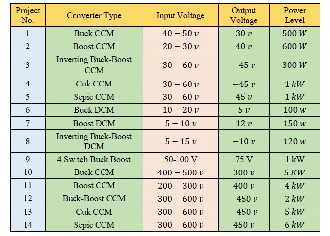
Our projects are designed by experts in the industry to reflect industry standards. By working through our projects, Learners will gain a practical understanding of what they will take on at a larger-scale in the industry. In total, there are 12 Projects that are available in this program.

Preparation of Converter Design report
Simulation and Design of Power Converters for EV using MATLAB and Simulink

Preparation of Converter Design report

In this project, a design report is prepared. The design report contains the details indicating the choices of inductance and capacitance levels in the design.

Design an interleaving DC/DC converter system for a data center application
Simulation and Design of Power Converters for EV using MATLAB and Simulink

Design an interleaving DC/DC converter system for a data center application

In this project, an interleaving DC/DC converter system is designed for a data center application. Its specifications are provided and the DC/DC converter system should have 85% ef…

Design and development of DC/AC H-bridge inverters  for microgrid applications
Simulation and Design of Power Converters for EV using MATLAB and Simulink

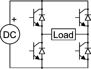
Design and development of DC/AC H-bridge inverters for microgrid applications

A DC/AC H-bridge inverter switches polarity of voltage, like any other inverters, but has a different circuit. In this project, the DC/AC H-bridge inverter is designed and develope…

Create a Project Workspace for MIC33030
Advanced PCB Design Using Altium

Create a Project Workspace for MIC33030

The students will be creating a project workspace for MIC33030. They will design a PCB using Altium ECAD software for a low-dropout voltage regulator (LDO) for 5V input, stepping d…

Create a project workspace for Arduino Mini
Advanced PCB Design Using Altium

Create a project workspace for Arduino Mini

In this project, the students will design a project workspace for Arduino Mini. The students will be developing the project based on the guidelines provided during the course.

Design and Simulation of Three-phase Uncontrolled and Controlled Rectifier Circuits for the Given Design Parameters
AC-DC Rectifiers, Harmonics and Related Standards

Design and Simulation of Three-phase Uncontrolled and Controlled Rectifier Circuits for the Given Design Parameters

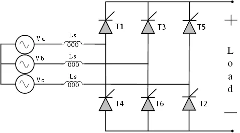
During this project, the students will design and simulate three-phase uncontrolled and controlled rectifier circuits based on the given input design parameters. They will design t…

Design and Simulation of a Closed Loop Single-phase High-power Factor Rectifiers
AC-DC Rectifiers, Harmonics and Related Standards

Design and Simulation of a Closed Loop Single-phase High-power Factor Rectifiers

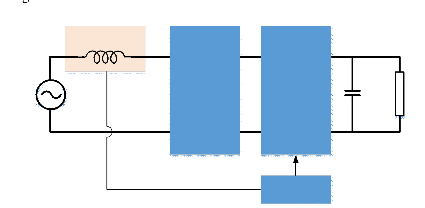
During this project, the students will design and simulate closed-loop single-phase high-power factor rectifiers based on the given input parameters.

Design of DC-DC SEPIC Converter
Fundamentals of DC-DC Converters

Design of DC-DC SEPIC Converter

A SEPIC Converter is a DC-DC converter having a unique circuit. In this project, the students will design a SEPIC Converter based on the given specifications. SEPIC converters are …

Design of MPPT Controller
Fundamentals of DC-DC Converters

Design of MPPT Controller

MPPT is used to send the maximum current required by the load. In this project, the students will design an MPPT controller based on the given specifications.

Simulation of All-Terrain Vehicle
Introduction to Physical Modeling using Simscape

Simulation of All-Terrain Vehicle

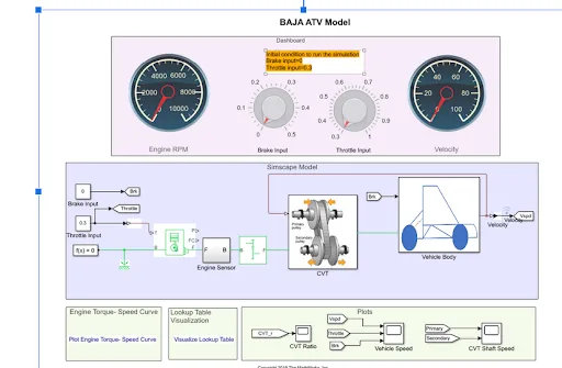
Learners are required to carry out a system-level simulation of an all-terrain vehicle using Simulink, Simscape, and Simscape Driveline. At the end of the project, learners should …

Loss Calculation of a DC/DC Converter using MATLAB
Design Concepts of Power Electronic Converters for Industries

Loss Calculation of a DC/DC Converter using MATLAB

Any device has power losses and the calculation of power losses helps in evaluating and improving the quality of the device. In this project, the students will perform loss calcula…

Modeling of 3 Phase Inverter for Electric Vehicle Application
Design Concepts of Power Electronic Converters for Industries

Modeling of 3 Phase Inverter for Electric Vehicle Application

Electric vehicles are replacing the conventional IC engine vehicles, and a three-phase inverter is one of the important components of an EV. In this project, the students will desi…

Fee

One fee.
Everything included.

Become job ready with our comprehensive industry focused curriculum for freshers & early career professionals

Premium
₹2,75,000
Inclusive of all chargesEMI from ₹14,375/month
  • Career Service Assurance
  • Personalized Career Services Mentorship
  • 1 Year Access
  • Personalized Page
  • Live Individual & Group Sessions
  • Personalized & Hands-On
  • Job-Oriented Industry Relevant Curriculum
Check eligibility →
FAQ

Questions,
answered.

Why do an online power converting course?

With the electric vehicle industry growing at 98% every year, companies manufacturing electric vehicles will need power engineering professionals, and this course equips you with such jobs. 

What will I learn in the certification course for electrical engineers?

You will gain comprehensive knowledge about DC-AC converters, modelling of power converters, and designing of power converters. 

What is the duration of the certified course on power converters?

The duration of the course is three months. In addition to this, you will need to do project work. 

What are the benefits of doing this course?

The best online course for electrical engineering offers many high-paying positions in top companies. You will be designing electric converters for future-ready electric vehicles. 

Which companies In India hire power engineers?

The top companies in India that need power engineers are ABB, Schneider Electric, Delta Electronics, BHEL, Tesla, and more. 

Who is eligible for this course?

You can pursue this course if you are an engineering graduate interested in power electronics engineering. This course is relevant for those seeking a career in the design, simulation, and development of power converters. 

What salary can I expect after completing this course?

The average salary you can expect as a power engineer is between Rs. 3 lakhs to Rs. 9 lakhs per annum.

Next step

Not sure it's
the right fit?

A counsellor will walk you through the syllabus, projects and fee options — and tell you honestly if another course suits you better.

Get the syllabus + a call back

We'll email the full syllabus and call within one working day.

By submitting you agree to our Terms and Privacy Policy.

Call usEnquire

Talk to a career counsellor

Free 20-minute call. We'll map the right course to where you want to work.

By submitting you agree to our Terms and Privacy Policy.