Menu


Modified on
What Beginners Should Know About The Sketcher Workbench?

Skill-Lync
A Sketcher Workbench is used to produce 2D geometries for use in the Workbench PartDesign.svg PartDesign Workbench, Workbench Arch.svg Arch Workbench, and other workbenches. The "constraints" in the Sketcher workbench enable 2D objects to adhere to exact geometrical requirements in terms of length, angles, and relationships (horizontality, verticality, perpendicularity, etc.). The constrained extent of 2D geometry is determined using a constraint solver, which also enables interactive exploration of the sketch's degrees of freedom.
This blog will help you explore in detail the importance of constraints in a Sketcher Workbench.
A) Understanding What Constraints Do
Constraining a sketch means not only providing the dimension values(which you may find from a question) of that particular sketch, it is arresting the degree of freedom of every component of that sketch from the origin.
For example,
_1671628853.png)
All the dimensions required to create the sketch are provided in the question above. With this information, when we try to create our sketch, we may notice that we still have an under-constrained sketch even after providing all dimensions from the question.
_1671628887.png)
Only after providing the length for the highlighted angled line is it as iso constraints.
_1671628922.png)
Example 2,
_1671628957.png)
Here the length and breadth of the rectangle are provided, but it still shows Under-Constraints. This is because, as mentioned earlier, whatever the sketch is, it should be arrested properly from the origin (horizontal and vertical axis) so that when we try to drag/move its position, it should stay in its original position where it is constrained.
_1671628995.png)
So, any two adjacent sides should be constrained from the horizontal and vertical axis.
_1671629047.png)
B)Types Of Constraints And Their Proper Use.
Constraints arrest or fix a sketch's position inside the sketcher workbench so that it does not move from its original position at later stages.
There are mainly two types of constraints: Dimensional Constraints and Geometrical Constraints.
Dimensional Constraints
When you give numerical values to a sketch, it is called Dimensional Constraints.
_1671629093.png)
Geometrical Constraints
Geometrical constraints include Symmetry, Coincidence, Parallelism, Tangency, etc.
_1671629133.png)
Try to use geometrical constraints whenever possible. By doing so, your sketch won’t be overcrowded with Dimensional Constraints.
Example:
The following image is properly constrained using two 70mm distances to the vertical axis from each point, a radius value of 90 from the origin to the centre construction of the elongated cylindrical hole, and a radius of 15mm is also applied.
_1671629173.png)
Instead of going with two 70mm distances, we can use a symmetry command between the two pints and the vertical axis. For that, we need to press ctrl and click two endpoints, along with that hold ctrl and select the vertical axis. Now click on Constraints Definition in the Dialogue Box and select symmetry.
_1671629217.png)
By doing this, you were able to make the same sketch iso-constraint without adding an extra 70mm dimension.
Above mentioned is a simple example that shows the possibilities of using Geometrical Constraints wherever possible. By doing this, we are eliminating the overuse of Dimensional Constraints, which makes your sketch look professional.
b) How to find out what constraints you need to add next to achieve iso- constraint?
Most of the time, we may face difficulty in understanding what constraints should be added next. Every time we may come across different sketches with different shapes. So it is important to understand how it should be constrained properly so that we will get it as iso-constraint. We can actually check them and apply constraints accordingly.
EXAMPLE 1, let’s start with a circle placed randomly on a position. If we try to click on the circle and drag it using a mouse, its size increases and decreases according to our movement.
_1671629292.png)
There we came to know that the circle radius/diameter needs to be constrained so that its size is fixed.
_1671629325.png)
After the diameter is fixed. If we try to move the circle, the size won’t increase or decrease, but you may notice its position moving according to our mouse movement. We can also check the sketch-solving status bar, which will display under constrained. There you may notice an orange dot indicating the midpoint. With all this information we will come into a conclusion where its position needs to be constrained.
Constraint the position by clicking on the center point of the circle and dimensioning it with the horizontal and vertical axis. By doing this, you will be getting a fully defined sketch with a sketch solver status bar showing iso-constrained.
_1671629369.png)
What if we create a circle at the origin? Here we only need to worry about the diameter/radius value. As we are creating the circle from the origin, it’s position is automatically defined by origin.
_1671629401.png)
EXAMPLE 2, let’s take an example of a line that is at an angle. The line is free to move anywhere on the plane.
_1671629446.png)
First, I constrain any one of the endpoints with horizontal and vertical axes.
_1671629480.png)
Now, if I try to drag it, two things will happen,
1. The line will rotate by taking center as the constrained point
2. Line length will increase as we drag it further.
Note:-After checking the line by dragging the mouse, use ctrl+z to bring it back to its original position
From the first point, we know that we now need to stop the rotation by giving an angle.
_1671629611.png)
There is a small misconception that if a sketch is green, it is now iso-constrained. It’s completely wrong. The above figure is an example to prove it wrong. You need to always check the sketch solver status bar for that. Turns out, it is under constraint. The second point needs to be constrained.
_1671629644.png)
Now we will resolve the second point in which the line length increases when we drag it using the mouse. For that, we will provide a dimension. By doing that, our sketch will be now iso- constrained.
_1671629678.png)
c) Multiple ways to make the same sketch iso-constrained/fully defined.
Method 1
_1671629750.png)
Here we constrained the sketch by providing relation on the first point from the origin, and in addition to that, an angle and length are provided.
Method 2
_1671629801.png)
In addition to point and angle, instead of line length, we constrained the second point from the horizontal axis instead of point and angle.
Method 3
_1671629840.png)
Here we constrain similar to the procedures mentioned in method 2, but instead of constraining the second point horizontally, we constrain it vertically.
Method 4
_1671629878.png)
Here both points are constrained from the horizontal and vertical axis.
So, from this, you may wonder whether there are multiple methods to constrain a sketch and what method you should choose. Well, you can choose any method, but preference may differ based on the situation.
d)Take care of these extra points after deleting any element
Let's take a situation where I have to delete the angular line from the following iso constraints sketch for some reason. Also, note that here the line's left starting point is given horizontal and vertical dimensions for making the point constraint properly, and the right ending point is constrained horizontally with 140mm.
_1671629922.png)
After deleting the line, I now only have a closed body i.e. the square of 50x50.
_1671629969.png)
Also, the dimensions that are related to the line are deleted as they are not required from now on.

Since we have a closed body, let's check the sketch solver status bar.

The sketch solver status bar shows two under-constrained points. How did this happen?

It has happened because, even though we managed to delete the line and dimensions related to that, our point still exists as a construction element. This is because we made the points dimensioned from the horizontal and vertical axis. By deleting the line and dimensions, the point continues to stay in its position because we fixed their position by constraining. Just delete those unwanted points manually and continue your work.

-
AVOID UNNECESSARY USE OF CONSTRUCTION ELEMENTS WHILE SKETCHING
Sometimes to make our sketching easy, we may depend on construction lines, or in general, we will convert some elements into construction. Try to avoid them if it is not necessary.
FOR EXAMPLE, let’s start with a simple sketch.

Here we have used some construction elements to create standard elements inside the sketch. But after our main elements turned green, we neglect constraining our construction elements, which in turn made the sketch under-constrained. Following are the mistakes that we can identify from the above sketch.
1)The endpoints of the construction lines are not constrained properly. If you are using any construction elements (in this case, it is not even necessary to create a construction element-reason will be explained later), you need to constrain it properly from the origin.
2) We have created a complex sketch using construction elements to draw a rectangle and two circles in the above example. In actual cases, these construction elements are not at all required. Providing them makes this sketch unprofessional and even makes it hard to understand.
3) Before making some horizontal and vertical construction elements to make our sketching easy, you should check whether this same result can be achieved using the horizontal and vertical axis. Here, we only need to constrain everything from the horizontal and vertical axes (origin).

By constraining everything from the origin, we are not only making our sketch look simple and clean but also avoiding some unnecessary containing of the construction element.
The above-mentioned example doesn’t mean you cannot use construction elements, you can use them but in the right situation. Let’s see another example where we can actually use them.
In EXAMPLE 2, we will also discuss some unnecessary areas where we use the construction elements. But this time we will try to avoid the unnecessary elements one by one in a step by step manner so that at the final stage we will understand the actual situation where we use the construction elements
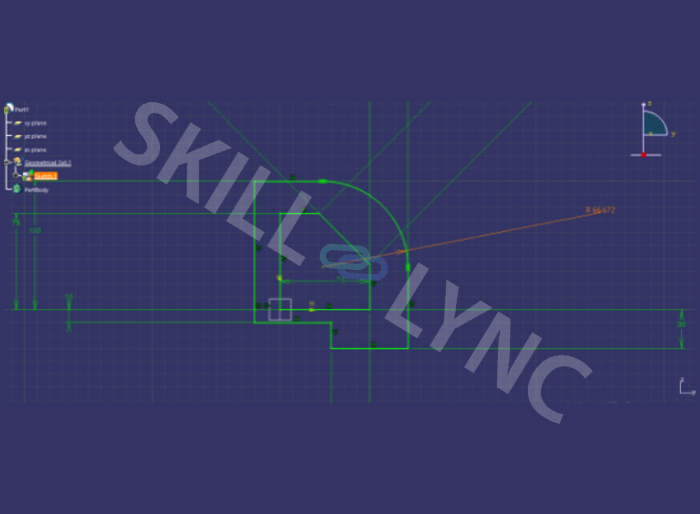
Here we are creating a cylindrical elongated hole from the origin at a distance of 200mm. The starting and ending point is determined by the 30-degree angle.

From the above image, we came to know that, after constraining the construction elements one by one, we were able to make it iso-constrained.
But the question here is whether we need this much of a construction element to create a single cylindrical elongated hole? The answer is no. Let's break down the possibilities of avoiding construction elements one by one.
1) Circular dia of 400 is not required here. Here we can create the Cylindrical Elongated Hole with a random radius value and later we can constrain them with the required radius value 200mm.

By doing this, we have removed the circular construction element. This change alone cannot be considered as a final solution for this sketch. We can eliminate more unwanted construction elements, in turn, make our sketch look more professional.
2) Here we can also remove the vertical construction line. Because as discussed earlier, we can directly give the 30degree angle from the vertical axis itself.

By doing this we are removing the extra dimensions that we provided on the construction line that has been drawn vertically from the origin. Even the construction line itself is avoided in this process.
Again we can remove a few more extra unwanted elements.
3) Here again, any of the two angular construction lines can be removed. Because as we discussed in earlier sessions of constraints, we can actually use the symmetry option here. So we can actually hold the control button and select the two points and vertical axis for the symmetry option.


So here, one more dimension constraint and construction line got removed.
4) Again if we look at the sketch carefully, do we actually need to extend the left angular construction line beyond the element? We can actually coincide it anywhere on the element that comes at its path. Here let us coincide it with the center construction line of the elongated cylindrical hole.


Note:- Here, instead of coinciding it at a later stage, you can snap directly to the center of the elongated hole at the time of the creation of the construction element.
Looking back at the image from which we started and the current image, we may notice a huge difference in both images. Here we trimmed down the remaining count of 1 single construction element. The point here is you can depend on construction elements while sketching, but before using them, make sure you actually need them. At your beginning stage of learning CATIA v5, you may need some unwanted construction lines to help you develop your complex sketch. But soon, when you are at an intermediate stage in your learning, you should avoid those unnecessary elements and learn to create your sketches without them.
3) Try To Arrange And Position The Dimensions Properly If Possible
While working on a sketch, it matters how well you are presenting it at the time of submission. You will be constraining your sketch using dimensional constraints. Position those dimensions so that you are actually working on a 2D drawing/drafting sheet.
Let’s look into some examples.
EXAMPLE 1
In the following example, even though everything is properly constrained, the way dimensions are placed is improper. It should be placed so that all dimensions are easily reachable for further editing and viewing.

EXAMPLE 2
In the following image, dimensions are placed at a far distance, which is also not recommended.
EXAMPLE 3
The below example shows the actual way of positioning dimensions. Here it is easily accessible as well as readable. If you notice, there is no intersection between the two dimensions.
Author

Navin Baskar
Author
Skill-Lync
Subscribe to Our Free Newsletter

Continue Reading
Related Blogs
Learn how to render a shock-tube-simulation and how to work on similar projects after enrolling into anyone of Skill-Lync's CAE courses.
09 May 2020
In this blog, read how to design the frontal BIW enclosure of a car (Bonnet) and learn how Skill-Lync Master's Program in Automotive Design using CATIA V5 will help you get employed as a design engineer.
09 May 2020
Tetrahedral is a four- nodded solid element that can be generated through the tria element by creating a volume and also through the existing volume of the geometry. These elements are used where the geometry has high thickness and complexity. The image attached below is a representation of a Tetra element. The Tetra element will have 4 triangular faces with four nodes joining them together
01 Aug 2022
A connector is a mechanism that specifies how an object (vertex, edge, or face) is connected to another object or the ground. By often simulating the desired behaviour without having to build the precise shape or specify contact circumstances, connectors make modeling simpler.
02 Aug 2022
One of the most crucial processes in carrying out an accurate simulation using FEA is meshing. A mesh is composed of elements that have nodes—coordinate positions in space that might change depending on the element type—that symbolise the geometry's shape.
03 Aug 2022
Author
Skill-Lync
Subscribe to Our Free Newsletter
Continue Reading
Related Blogs
Learn how to render a shock-tube-simulation and how to work on similar projects after enrolling into anyone of Skill-Lync's CAE courses.
09 May 2020
In this blog, read how to design the frontal BIW enclosure of a car (Bonnet) and learn how Skill-Lync Master's Program in Automotive Design using CATIA V5 will help you get employed as a design engineer.
09 May 2020
Tetrahedral is a four- nodded solid element that can be generated through the tria element by creating a volume and also through the existing volume of the geometry. These elements are used where the geometry has high thickness and complexity. The image attached below is a representation of a Tetra element. The Tetra element will have 4 triangular faces with four nodes joining them together
01 Aug 2022
A connector is a mechanism that specifies how an object (vertex, edge, or face) is connected to another object or the ground. By often simulating the desired behaviour without having to build the precise shape or specify contact circumstances, connectors make modeling simpler.
02 Aug 2022
One of the most crucial processes in carrying out an accurate simulation using FEA is meshing. A mesh is composed of elements that have nodes—coordinate positions in space that might change depending on the element type—that symbolise the geometry's shape.
03 Aug 2022
Related Courses