AUTOSAR Interview Questions: 28 Answers on RTE, BSW, COM Stack and Adaptive
Model answers to the AUTOSAR questions freshers and 2-5-year engineers face: Classic vs Adaptive, the layered architecture, SWCs, ports and runnables, the COM stack, OS and EcuM, DEM/DCM, NvM, ARXML and SOME/IP. Every answer is checked against the R25-11 specifications, with a worked signal trace from Rte_Write to CAN frame bytes.

In short
- AUTOSAR interviews for freshers test the layers (application, RTE, Basic Software, MCAL), SWCs, ports and runnables, and the difference between sender-receiver and client-server communication.
- Engineers with 2-5 years are pushed further. Expect to trace a signal through RTE → COM → PduR → CanIf → CAN driver and explain COM transfer properties. Diagnostics (DEM debouncing, DCM, the UDS status byte), NvM, ARXML configuration and the Adaptive Platform (ara::com, SOME/IP) also come up.
- Every answer below is checked against the current AUTOSAR release, R25-11 (published 27 November 2025), and names the specification it comes from. Follow-up questions are where vague answers fall apart.
Most AUTOSAR interview questions fall into nine groups:
- Classic vs Adaptive Platform
- the layered architecture
- software components and ports
- runnables and RTE events
- the communication stack
- the OS and ECU state management
- diagnostics
- non-volatile memory
- the ARXML-based configuration workflow
A fresher is expected to explain the vocabulary correctly. An engineer with two to five years is expected to explain what happens at run time: which function calls which, when data is copied, and why a frame left the ECU when it did.
This guide gives model answers for both levels. It includes two worked examples that interviewers like to turn into whiteboard questions. In the first, a vehicle-speed value travels from a software component to the bytes of a CAN frame. In the second, a diagnostic event is debounced into a stored trouble code.
A note on honesty: we don't have any company's internal question bank, and nothing here claims to be one. The questions are the topics AUTOSAR roles are built around. The answers come from the AUTOSAR specifications themselves, so you can defend every line.
How should you use these AUTOSAR interview questions?
Each question is tagged:
- (fresher): you should be able to answer it from a course or a project.
- (2-5 yrs): interviewers expect working experience with an AUTOSAR stack, a configuration tool and a debugger.
Read the fresher questions first. If you can explain the worked examples without looking, you are ready for most technical rounds.
If your C fundamentals are shaky, fix those first with our embedded C interview questions. AUTOSAR code is C, and the C round usually comes before the AUTOSAR round.
What is AUTOSAR, and why do carmakers use it?
1. What is AUTOSAR? (fresher)
AUTOSAR (AUTomotive Open System ARchitecture) is a set of standards for the software architecture of vehicle electronic control units (ECUs). It is written by a partnership of carmakers, suppliers and tool vendors.
Work began in 2002 with BMW, Bosch, Continental, DaimlerChrysler and Volkswagen, and Siemens VDO joined soon after. Classic Platform Release 1.0 came out in May 2005, and the partnership now lists more than 350 partners.
The point is reuse. A software component written against standard interfaces can move to a different ECU or microcontroller without being rewritten. A supplier can also deliver basic software that any carmaker's application code can sit on.
2. What is the difference between the Classic and Adaptive Platforms? (fresher)
AUTOSAR describes the Classic Platform as its solution for embedded systems with hard real-time and safety constraints. That covers engine, brake, body and battery-management ECUs on small microcontrollers. The Adaptive Platform is its solution for high-performance computing ECUs, such as central computers for driver assistance.
The first Adaptive release was 2017-03 (March 2017). AUTOSAR's own design document says Adaptive will not replace Classic. The two run side by side in the same vehicle and talk to each other.
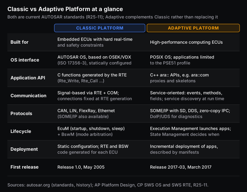
The one-line answer interviewers like: Classic is signal-based and statically configured, while Adaptive is service-based and partly dynamic. The RTE specification says plainly that the Classic RTE "shall support static communication only". Every sender and receiver is known when the RTE is generated. On Adaptive, applications find services at run time through service discovery.
3. What is AUTOSAR Foundation? (fresher)
Foundation is the third standard. It holds the parts common to Classic and Adaptive, such as bus protocols. The SOME/IP protocol specification, for example, is a Foundation document, because both platforms use it.
4. How are AUTOSAR releases named? (fresher)
Classic used numbers (1.0 up to 4.x) until 2018. AUTOSAR then moved to year-month names such as 19-11, and added an "R" prefix from 2020 (R20-11).
Since then there has been one release a year, each in late November: R21-11, R22-11, R23-11, R24-11 and R25-11. If you are asked which release your project uses, know it. Projects usually stay on the release they started with, and module names differ between releases.
What are the layers of the AUTOSAR Classic architecture?
5. Name the layers and what each one does. (fresher)
At the top level there are three layers: Application, Runtime Environment (RTE) and Basic Software (BSW), running on a microcontroller. The BSW is split into the Services layer, the ECU Abstraction layer, the Microcontroller Abstraction Layer (MCAL) and Complex Drivers.
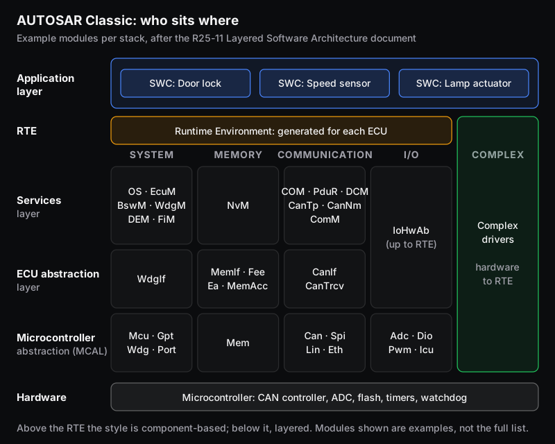
| Layer | Job | Hardware dependence |
|---|---|---|
| Application | Vehicle functions as software components (SWCs) | None |
| RTE | Communication between SWCs and with BSW; makes SWCs independent of which ECU they are mapped to | Generated individually for each ECU |
| Services | OS, network communication, NVRAM, diagnostics, ECU state and mode management, watchdog management | Mostly µC- and ECU-independent |
| ECU Abstraction | Uniform access to peripherals and external devices, wherever they are connected | µC-independent, ECU-hardware-dependent |
| MCAL | Drivers with direct access to the microcontroller and its internal peripherals | µC-dependent |
| Complex Drivers | Special-purpose functions from hardware up to the RTE | May depend on anything |
6. What is the difference between MCAL and the ECU Abstraction Layer? (fresher)
The MCAL is the lowest BSW layer. It holds drivers for the microcontroller's own peripherals (ADC, DIO, PWM, CAN controller, SPI, GPT timers, watchdog, MCU clock), so its implementation depends on the microcontroller. It makes the layers above independent of the chip.
The ECU Abstraction layer makes them independent of the board. It offers one API whether a device is inside the microcontroller or outside it on SPI, and regardless of which pin it is wired to.
Example: a door-ajar switch. Whether the switch is read through an on-chip DIO pin or an external I/O expander on SPI, the I/O Hardware Abstraction (IoHwAb) gives the application the same signal. That wiring knowledge lives in the ECU Abstraction layer, not in the SWC.
7. When would you use a Complex Device Driver? (2-5 yrs)
Use one when the standard layering cannot do the job. The AUTOSAR layered-architecture document lists three cases:
- a device AUTOSAR does not specify;
- a function with very high timing constraints;
- migration of legacy code.
Typical examples are injection and ignition timing in an engine ECU, or a custom sensor interface. A CDD can reach the hardware directly and talks to the application through the RTE. The cost is portability: it is the one part of the stack that is not standardised.
8. What does the RTE actually do? (fresher)
The RTE is code generated for one specific ECU. It implements the connections drawn on the Virtual Functional Bus (VFB). The AUTOSAR methodology defines the VFB as "an abstract communication mechanism that allows software components to interact", independent of any ECU or network.
When an SWC writes to a port, the RTE decides what that means on this ECU:
- a buffer copy, if the receiver is on the same core;
- an inter-partition (IOC) transfer, if it is on another partition;
- a call into COM, if the receiver is on another ECU.
The RTE also activates runnables on RTE events (question 12) and handles mode switching. A good answer adds that the RTE is not a scheduler of its own: runnables are mapped to OS tasks, and the OS schedules the tasks.
What are SWCs, ports, interfaces and runnables?
9. What types of software components are there? (fresher)
The Software Component Template defines an atomic component as one that "cannot be further decomposed and distributed across multiple ECUs". Atomic types include:
- Application SWC
- Sensor-Actuator SWC
- Complex Device Driver SWC
- ECU Abstraction SWC
- Service SWC
- Service Proxy SWC
- NV Block SWC
A Composition groups SWCs into a hierarchy for design purposes, and a Parameter SWC provides calibration parameters. Only atomic SWCs contain runnables and code.
10. What are ports and port interfaces? Name the interface types. (fresher)
A port is a component's connection point:
- a P-port (provide) offers data or a service;
- an R-port (require) consumes it;
- a PR-port does both.
Every port is typed by a port interface. There are six:
- Sender-Receiver: data elements.
- Client-Server: operations with arguments.
- Mode-Switch: mode declaration groups.
- Parameter: calibration data.
- NvData: non-volatile data.
- Trigger: a trigger with no data.
Two ports can only be connected if their interfaces are compatible.
11. Sender-receiver vs client-server: what is the difference? (fresher, with a 2-5 yrs follow-up)
| Sender-receiver | Client-server | |
|---|---|---|
| What flows | Data elements, one direction | Operation request, then a response with return value and OUT arguments |
| Who starts it | The sender writes when it has data | The client requests; the server runnable is invoked by the RTE |
| Multiplicity | 1:n and n:1 both supported | n:1 supported (many clients, one server); 1:n is not |
| Semantics | Last-is-best (data) or queued (events) | Synchronous (client blocks) or asynchronous (client collects the result later) |
| Typical RTE API | Rte_Write / Rte_Read, Rte_Send / Rte_Receive, Rte_IWrite / Rte_IRead | Rte_Call, plus Rte_Result for asynchronous calls |
| Typical use | Vehicle speed, temperature, switch states | "Read this calibration block", "compute a checksum", service calls to NvM or DEM |
The follow-up for experienced candidates: last-is-best vs queued. The RTE specification says that with data distribution "the last received value is of interest". With event distribution "the whole history of received events is of interest, hence they must be queued on receiver side".
This is set by the data element's swImplPolicy (standard or queued). A queued element uses Rte_Send and Rte_Receive. A last-is-best element uses Rte_Write and Rte_Read.
The standard trap question is "Your button-press counter misses presses. Why?" The answer: someone modelled an event as last-is-best data.
12. What is a runnable, and what triggers it? (fresher)
A runnable entity is "the smallest code-fragment" of an atomic SWC "executed under control of the RTE". In code it is a C function.
Runnables are started by RTE events. The common ones are:
- TimingEvent: periodic, for example every 10 ms.
- DataReceivedEvent: new data arrived on an R-port.
- OperationInvokedEvent: a client called this server operation.
- InitEvent: run once at start-up.
- BackgroundEvent: run when nothing else is ready.
- DataReceiveErrorEvent, DataSendCompletedEvent, SwcModeSwitchEvent and AsynchronousServerCallReturnsEvent, among others.
During configuration, each event is mapped to an OS task, with a position in that task. That mapping decides the runnable's priority and timing.
13. Explicit vs implicit communication: when is the data actually copied? (2-5 yrs)
With explicit access (Rte_Write, Rte_Read), the data moves at the moment of the call.
With implicit access (Rte_IWrite, Rte_IRead), the RTE reads the configured inputs into a copy before the runnable starts and writes the outputs after it ends. The specification also requires that implicitly read data "shall not change during execution of the runnable".
Implicit access gives you a consistent snapshot, which control algorithms like, but it costs RAM for the copies. It also means a value written mid-runnable is not visible to anyone until the runnable returns. Being able to explain that difference with a timing sketch is a good sign of real project experience.
How does a signal travel through the AUTOSAR COM stack? (worked example)
14. Trace one signal from an SWC to the CAN bus. (2-5 yrs, the most common whiteboard question)
Take an illustrative configuration:
- A speed-sensor SWC has a runnable on a 10 ms TimingEvent.
- It provides the data element VehSpd: uint16, scaled at 0.01 km/h per bit.
- VehSpd goes to another ECU in an 8-byte CAN frame with ID 0x1A0.
- The signal sits at bit position 16, 16 bits long, little-endian (Intel byte order).
The vehicle is doing 72.50 km/h.
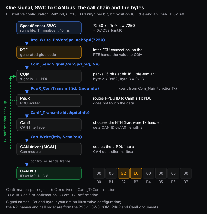
- Scale. 72.50 ÷ 0.01 = 7250 = 0x1C52. The runnable calls
Rte_Write_PpVehSpd_VehSpd(7250). - RTE. The port is connected to a receiver on another ECU, so the generated RTE code calls
Com_SendSignal(SignalId, &value). Its signature isuint8 Com_SendSignal(Com_SignalIdType SignalId, const void* SignalDataPtr). - COM. COM copies the value into its I-PDU buffer at bit 16, little-endian. Byte 2 becomes 0x52 and byte 3 becomes 0x1C. When the I-PDU is due (question 16), Com_MainFunctionTx calls
PduR_ComTransmit(TxPduId, &PduInfo). - PduR. The PDU Router looks up the routing path and calls
CanIf_Transmit(TxPduId, &PduInfo). It does not change the data. - CanIf. The CAN Interface checks it is initialised and picks the driver and the hardware transmit handle (HTH). It then calls
Can_Write(Hth, &PduInfo)with a Can_PduType holding the CAN ID (0x1A0), the length (8), a pointer to the data and a handle for the confirmation. - CAN driver. The MCAL driver copies the frame into a CAN controller mailbox, and the controller arbitrates for the bus.
- Confirmation. After a successful transmission the driver calls
CanIf_TxConfirmation. CanIf callsPduR_CanIfTxConfirmation, which callsCom_TxConfirmation.
The frame on the wire is ID 0x1A0, data 00 00 52 1C 00 00 00 00. The other bytes would hold other signals in a real I-PDU.
Two follow-ups interviewers often add:
- "How long is that frame on a 500 kbit/s bus?" A classic CAN frame with an 11-bit ID and 8 data bytes is 111 bits without stuffing and at most 135 bits with worst-case bit stuffing, by the standard formula in Davis et al. (2007). At 2 µs per bit, that is 270 µs worst case. Sent every 20 ms (50 frames per second), it uses 6,750 bit/s, or 1.35% of the bus.
- "The I-PDU is periodic at 20 ms but the runnable writes every 10 ms. What happens?" With last-is-best data, every second value is overwritten before it is sent. That is fine for speed, but wrong for anything that counts events.
15. What is the difference between a signal, an I-PDU and an L-PDU? (fresher)
A signal is one value (VehSpd). An I-PDU (interaction-layer PDU) is the block of bytes COM builds from several signals. An L-PDU is the data-link-layer unit that CanIf hands to the driver: the CAN frame payload plus its ID and length.
The layered-architecture document defines the general terms:
- the SDU (service data unit) is the data an upper layer passes down;
- the PCI (protocol control information) is what a layer adds;
- the PDU is SDU plus PCI.
The PDU of one layer is the SDU of the layer below.
16. What are COM transfer properties and transmission modes? (2-5 yrs)
The two settings decide when a frame leaves:
- The signal has a transfer property: PENDING, TRIGGERED, TRIGGERED_ON_CHANGE, or the "without repetition" versions of the last two.
- The I-PDU has a transmission mode: DIRECT, PERIODIC, MIXED or NONE.
From the COM specification:
- A TRIGGERED signal in a DIRECT or MIXED I-PDU makes COM send the I-PDU (number of repetitions + 1) times, starting "within the next main function at the latest".
- TRIGGERED_ON_CHANGE does the same, but only if the new value differs from the last one sent.
- A PENDING signal never causes a transmission by itself. It goes out the next time the I-PDU is sent for any other reason.
- COM never transmits an I-PDU with mode NONE on its own.
In the worked example, PENDING plus a PERIODIC 20 ms I-PDU gives a steady 50 frames per second. Switching to TRIGGERED_ON_CHANGE plus MIXED gives periodic frames plus an extra one whenever the speed changes.
17. Why does the PDU Router exist, and what is CanTp for? (2-5 yrs)
COM and DCM should not need to know which bus a PDU goes out on. The PDU Router routes each I-PDU by ID to the right lower layer: CanIf, CanTp, LinIf, the FlexRay interface or the socket adapter for Ethernet. It can also send one I-PDU to several destinations, or route between two buses on a gateway ECU.
CanTp is the CAN transport protocol (ISO 15765-2). It splits messages longer than one frame into segments and reassembles them. The layered-architecture document lists its use as "ISO Diagnostics (DCM), large PDU transport on standard CAN bus".
On classic CAN, an ISO-TP single frame carries at most 7 bytes of data. A longer UDS response therefore goes DCM → PduR → CanTp → CanIf as several frames. CAN FD frames can carry up to 64 bytes, which reduces, but does not remove, the need for segmentation.
What do interviewers ask about the AUTOSAR OS and ECU state management?
18. How is the AUTOSAR OS related to OSEK, and what are scalability classes? (2-5 yrs)
The AUTOSAR OS specification uses ISO 17356-3 (the OSEK/VDX OS) as its basis and extends it. It adds schedule tables, stack monitoring, protection features and multi-core support. The features are grouped into four scalability classes:
| Scalability class | Adds | Hardware needed |
|---|---|---|
| SC1 | OSEK OS, counters, schedule tables, stack monitoring | None beyond a timer |
| SC2 | SC1 + timing protection, global time synchronisation, ProtectionHook | High-priority timer interrupt |
| SC3 | SC1 + memory protection, OS-Applications, service protection, trusted functions | MPU, privileged and non-privileged modes |
| SC4 | SC2 + SC3 features | Both |
Two details score points:
- SC3 and SC4 must always use extended status.
- Memory protection needs a hardware MPU and works per OS-Application. The OS specification gives satisfying safety constraints as one reason to use it, which is why ECUs that host software of different safety levels look at SC3 or SC4.
19. What is the difference between EcuM and BswM? (2-5 yrs)
The ECU State Manager (EcuM) handles the phases of the ECU's life: STARTUP, UP, SHUTDOWN, SLEEP and OFF. It also validates wakeup sources, so unintended wakeups can be ignored.
The BSW Mode Manager (BswM) does the mode arbitration once the ECU is up. It evaluates rules and runs action lists.
The EcuM specification says the UP phase starts once the BSW scheduler has started and BswM_Init has been called. From then on, BswM action lists (integration code) do the rest of the BSW initialisation and start the RTE. That includes NvM_ReadAll, followed by initialising COM, DEM and FiM. The RTE can start once NvM and COM are initialised.
So the honest answer to "who starts the RTE?" in a modern stack is: the integrator, through BswM.
What are the AUTOSAR diagnostics questions (DEM and DCM)?
20. What is the difference between DEM and DCM? (fresher)
The Diagnostic Event Manager (DEM) collects pass/fail reports from monitors, debounces them, stores DTCs (diagnostic trouble codes) with freeze frames in non-volatile memory, and maintains the UDS status byte.
The Diagnostic Communication Manager (DCM) talks to the tester. It receives UDS (ISO 14229-1) requests, checks them and builds responses, fetching DTC data from DEM when needed.
DCM has three submodules:
- DSL (Diagnostic Session Layer): sessions and response timing.
- DSD (Diagnostic Service Dispatcher): checks a request is valid in the current session and security level, then dispatches it.
- DSP (Diagnostic Service Processing): executes the service and assembles the response.
21. How does counter-based debouncing work? (2-5 yrs, worked example)
A monitor reports PREFAILED or PREPASSED each time it runs. With counter-based debouncing, DEM keeps an internal counter per event:
- Each PREFAILED adds the increment step, clamped at the failed threshold.
- Each PREPASSED subtracts the decrement step, clamped at the passed threshold.
- A FAILED or PASSED report jumps the counter straight to the threshold.
- Optional jump-down resets the counter to a configured value before counting down after a failure.
DEM maps the internal counter linearly onto the UDS fault detection counter, which runs from −128 to +127.
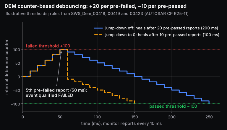
Take illustrative values: failed threshold +100, passed threshold −100, step +20 up and −10 down, and a monitor that reports every 10 ms.
- Five PREFAILED reports take the counter from 0 to 100, so the event is qualified failed at 50 ms.
- To heal, the counter must fall from +100 to −100: 200 ÷ 10 = 20 PREPASSED reports, or 200 ms.
- With jump-down to 0, the first PREPASSED report resets the counter to 0 and then subtracts 10. It reaches −100 after 10 reports, or 100 ms.
22. Walk me through the UDS DTC status byte. (2-5 yrs)
The status byte has eight bits, as defined in ISO 14229-1 and quoted in the DEM specification:
- bit 0 testFailed: the most recent test failed.
- bit 1 testFailedThisOperationCycle.
- bit 2 pendingDTC: a failure in the current or last completed operation cycle.
- bit 3 confirmedDTC: detected often enough to be stored long-term.
- bit 4 testNotCompletedSinceLastClear.
- bit 5 testFailedSinceLastClear.
- bit 6 testNotCompletedThisOperationCycle.
- bit 7 warningIndicatorRequested.
After a clear, DEM sets the byte to 0x50 (bits 4 and 6). In the debounce example, the first failed qualification sets bits 0, 1, 2 and 5 and clears bits 4 and 6. That gives 0x27, or 0x2F if bit 3 is also set.
Whether bit 3 is set on the first failure depends on the event's confirmation threshold. DEM sets confirmedDTC when the failure counter + 1 reaches DemEventConfirmationThreshold, so a threshold of 1 confirms immediately. A threshold of 2 needs failures in two operation cycles.
23. A tester sends 0x22 F1 90. What happens inside the ECU? (2-5 yrs)
0x22 is ReadDataByIdentifier, and 0xF190 is the data identifier conventionally used for the VIN. The request comes up the bus stack through the CAN driver, CanIf, CanTp and PduR to DCM. Then:
- DSL checks the session and timing.
- DSD confirms that 0x22 is allowed in the active session and security level.
- DSP checks the length and reads the DID from its configured source, such as an SWC port, a C callback or an ECU signal.
A positive response starts with 0x62 (the request ID + 0x40). A negative response is 0x7F, 0x22, then a negative response code: for example 0x13 for a wrong length, or 0x78 "response pending" if the data needs more time.
What should you know about NvM and the memory stack?
24. What are the NvM block types, and how does data reach flash? (2-5 yrs)
The NVRAM Manager supports three block management types:
- NVM_BLOCK_NATIVE: one NV block, one RAM block, an optional ROM default.
- NVM_BLOCK_REDUNDANT: two NV copies, for data that must survive corruption.
- NVM_BLOCK_DATASET: up to 255 NV blocks selected by index, such as several calibration sets.
NvM data is mostly read at start-up with NvM_ReadAll and written at shutdown with NvM_WriteAll. Single blocks can also be written during operation with NvM_WriteBlock.
The path down is NvM → MemIf → Fee (flash EEPROM emulation) or Ea (EEPROM abstraction) → driver. Here the release matters, and it is a good way to show you are current. In the R25-11 layered architecture, Fee and Ea call the Memory Access module (MemAcc), which calls the Memory driver (Mem). The document's change history records "Removed Fls and Eep" in R25-11.
Older stacks, and many projects still in production, use Fee → Fls and Ea → Eep. Say which one your project used.
How do ARXML and the AUTOSAR configuration workflow work?
25. What is ARXML, and what is the Classic workflow from system design to code? (fresher, with a 2-5 yrs follow-up)
ARXML is AUTOSAR's XML exchange format. The ECU Configuration specification says AUTOSAR XML files were chosen as the exchange format, and a description may be split over many files that are merged.
The methodology runs roughly like this:
- Design SWCs and connect them on the VFB (system description).
- Map SWCs to ECUs and signals to frames (system design).
- Generate an ECU Extract, "an extract of the System description for setting up an ECU Configuration".
- Configure the BSW and RTE for that ECU (ECU configuration values).
- Generate the RTE and BSW code, then compile and link with the SWC code.
Tools differ by company:
- Vector's DaVinci Configurator Classic configures, validates and generates the BSW and RTE.
- MATLAB's AUTOSAR Blockset can import ARXML (arxml.importer) to create Simulink models of components, and export them again.
The follow-up for experienced candidates: configuration classes. A parameter can be fixed at pre-compile time (in generated source), at link time (in a separately compiled object) or at post-build time, where it can be changed in flash without recompiling the module. Modules can also support several post-build variants, so one software build can serve more than one configuration.
Our guide to testing ECU software covers how the generated code is then verified.
What do interviewers ask about the Adaptive Platform and SOME/IP?
26. What are the main parts of the Adaptive Platform? (2-5 yrs)
An Adaptive machine runs a POSIX operating system. Adaptive applications are restricted to PSE51, a single-process POSIX profile, chosen for portability and freedom from interference.
Functionality comes from Functional Clusters with C++ APIs under the ara:: namespace. The ones asked about most are:
- Execution Management (EM) launches and stops applications.
- State Management (SM) decides which applications should run in which machine state and commands EM.
- Communication Management (ara::com) provides service-oriented communication. A service is made of events, methods and fields.
Generated proxies on the client side and skeletons on the server side hide the transport. A Service Registry handles discovery. Deployment is described in manifests: execution, service-instance and machine manifests.
27. Describe the SOME/IP header. (2-5 yrs)
SOME/IP (Scalable service-Oriented MiddlewarE over IP) carries service calls and events over Ethernet. Its header is 16 bytes:
- Message ID (32 bits): a 16-bit Service ID plus a 16-bit Method ID.
- Length (32 bits).
- Request ID (32 bits): Client ID plus Session ID.
- Protocol Version, Interface Version, Message Type and Return Code: 8 bits each.
Points that catch people out:
- Length counts from the Request ID to the end of the message, so it is 8 + payload. A 4-byte payload gives Length = 12 and a 20-byte message.
- Method IDs 0x0000-0x7FFF are recommended for methods and 0x8000 upward for events.
- Message types: 0x00 REQUEST, 0x01 REQUEST_NO_RETURN (fire and forget), 0x02 NOTIFICATION, 0x80 RESPONSE and 0x81 ERROR. The 0x20 bit marks a SOME/IP-TP segment.
- The Session ID wraps from 0xFFFF back to 0x01.
Service discovery (SOME/IP-SD) is how clients find offered services and subscribe to event groups.
28. Can a Classic ECU use SOME/IP? (2-5 yrs)
Yes. AUTOSAR's Adaptive design document notes that the Classic Platform "already incorporates SOME/IP". That is how an Adaptive central computer and Classic zone or domain ECUs exchange data over automotive Ethernet. Adaptive Communication Management also supports DDS, zero-copy IPC inside a machine, and a signal-to-service translation for talking to signal-based networks.
For a wider view of CAN, LIN, FlexRay and Ethernet, see our overview of automotive communication protocols.
How should freshers and experienced engineers prepare?
- Freshers: be able to draw the layer diagram from memory and name two modules in each layer. Explain sender-receiver vs client-server with an example from your project. Write a runnable that reads one port and writes another using Rte_Read and Rte_Write. Build one small SWC end to end in a tool, for example Simulink with AUTOSAR Blockset, and be ready to show the ARXML it produces.
- 2-5 years: rehearse the signal trace above with your own project's names, IDs and timing. Know your project's release (4.x or R2x-11), OS scalability class, transfer properties and debounce settings. Have one real debugging story ready: a frame that didn't go out, a DTC that wouldn't heal, an NvM block that came back with defaults. Interviewers use these to tell configuration-tool users from engineers who understand the stack.
- Both: say "it depends on the configuration" only when you can name the parameter it depends on.
Skill-Lync's Introduction to Automotive Embedded Systems and AUTOSAR course covers this set: AUTOSAR basics and SWCs, the BSW and MCAL, diagnostics and the memory stack, the RTE, complex drivers and the OS, and SWC modelling in MATLAB. For a broader embedded foundation, see the PG Program in Embedded Systems for EV Applications. For the testing side of model-based AUTOSAR work, see Software Verification and Validation for Model-Based Development.
Frequently asked questions
Is AUTOSAR hard to learn for a fresher?
The concepts are not hard. The vocabulary is large and the specifications are long: the RTE specification alone runs to more than 1,600 pages. Learn the layers, ports, runnables and the COM path first, then build one small component in a tool. Most fresher interviews stay at that level.
Which AUTOSAR release should I study?
Learn the concepts from the current release, R25-11. They have been stable for years. Be aware that many production projects use older 4.x releases, where some module names differ, for example Fls and Eep in the memory stack. If you have project experience, know exactly which release it used.
Do I need to know C++ for AUTOSAR jobs?
For Classic Platform roles, embedded C is what matters, because the RTE API and the BSW are C. For Adaptive Platform roles you need modern C++, since the ara:: APIs are C++ and applications run on a POSIX operating system.
What is the difference between AUTOSAR and OSEK?
OSEK/VDX (standardised as ISO 17356) is an operating system and communication standard. AUTOSAR covers the whole ECU software architecture. Its Classic OS is built on OSEK OS and adds schedule tables, timing and memory protection, OS-Applications and multi-core support.
Are DaVinci and EB tresos part of AUTOSAR?
No. Vector's DaVinci Configurator and Elektrobit's EB tresos Studio are commercial tools for configuring, validating and generating AUTOSAR basic software (and, for DaVinci, the RTE). AUTOSAR standardises the interfaces, behaviour and exchange formats, while vendors provide the implementations and tools. Interviewers care more that you understand what a tool generates than which tool you used.
Sources and further reading
- AUTOSAR, Layered Software Architecture, Classic Platform R25-11 (27 Nov 2025)
- AUTOSAR, Specification of RTE Software, CP R25-11
- AUTOSAR, Software Component Template, CP R25-11
- AUTOSAR, Specification of Communication, CP R25-11
- AUTOSAR, Specification of PDU Router, CP R25-11
- AUTOSAR, Specification of CAN Interface, CP R25-11
- AUTOSAR, Specification of Operating System, CP R25-11
- AUTOSAR, Specification of ECU State Manager, CP R25-11
- AUTOSAR, Specification of Diagnostic Event Manager, CP R25-11
- AUTOSAR, Specification of Diagnostic Communication Manager, CP R25-11
- AUTOSAR, Specification of NVRAM Manager, CP R25-11
- AUTOSAR, Methodology for Classic Platform and Specification of ECU Configuration, CP R25-11
- AUTOSAR, Explanation of Adaptive Platform Design, AP R25-11
- AUTOSAR, SOME/IP Protocol Specification, Foundation R25-11
- AUTOSAR, Standards, History and Partners pages (accessed 15 Nov 2026)
- Vector, DaVinci Configurator Classic product page, and Elektrobit, EB tresos Studio product page (accessed 15 Nov 2026)
- MathWorks, arxml.importer, AUTOSAR Blockset documentation (accessed 15 Nov 2026)
- CSS Electronics, UDS Explained: A Simple Intro (accessed 15 Nov 2026)
- Davis, Burns, Bril and Lukkien, Controller Area Network (CAN) schedulability analysis: Refuted, revisited and revised, Real-Time Systems 35 (2007)