Wiring harness routing & packaging Rules Week 3 Challenge
Solution
A1
1) Make a plane entry point.
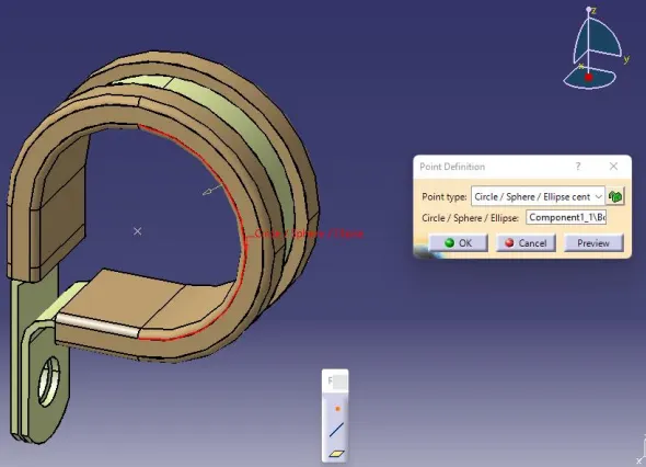
2) Make a point for the exit plane.
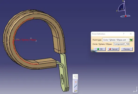
3) Create a plane
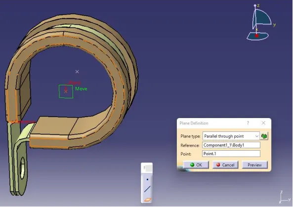
4) Make a base plane
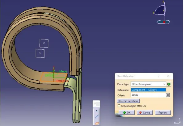
5) Define the clip as an electrical support after switching to the 'Electrical Part Design' workbench. Click on define support, then select the clip.
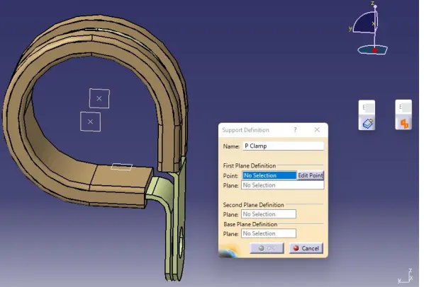
6) Definitions of the clip's entry, exit, and base
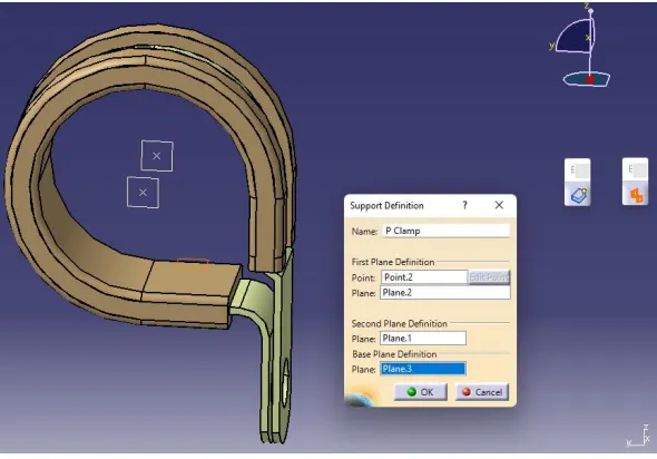
7) Two entries and exits should be available. Therefore, define the second entry and exit.
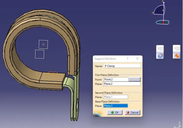
8) Hide all the existing planes (this step is not mandatory)
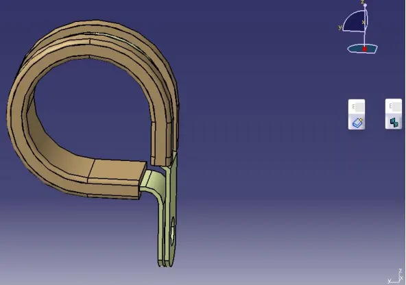
The clip is prepared for usage, as seen in the below figure, and the properties have been saved
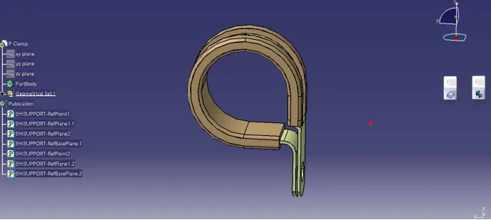
A2
1) Define point and axis for bundle and backshell connection point
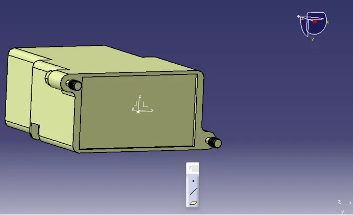
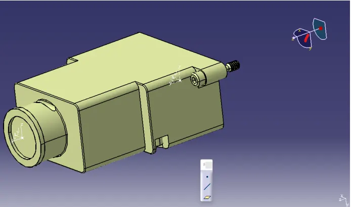
2) Switch to ‘Electric Part Design’ workbench and define the part as a backshell
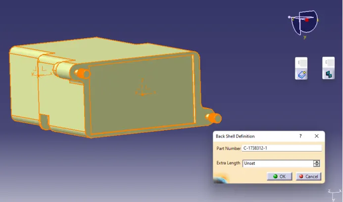
3) Define backshell connection point
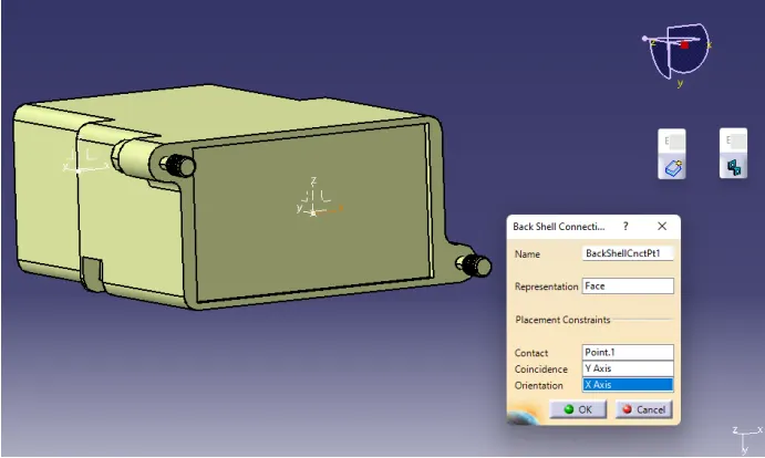
4) Define bundle connection point
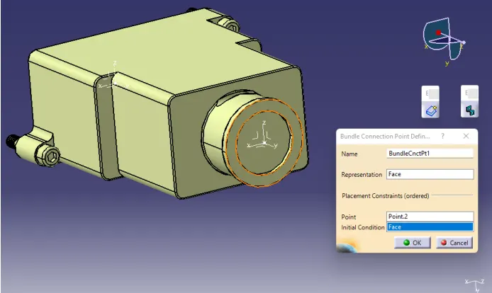
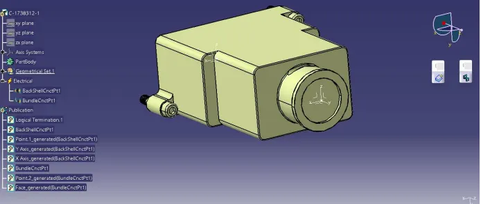
The backshell is prepared for usage, as seen in the below figure, and the properties have been saved
A3
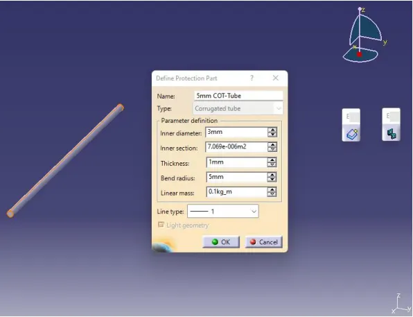
Create corrugated tubes by:
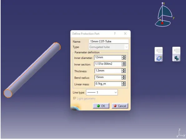
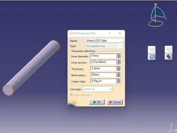
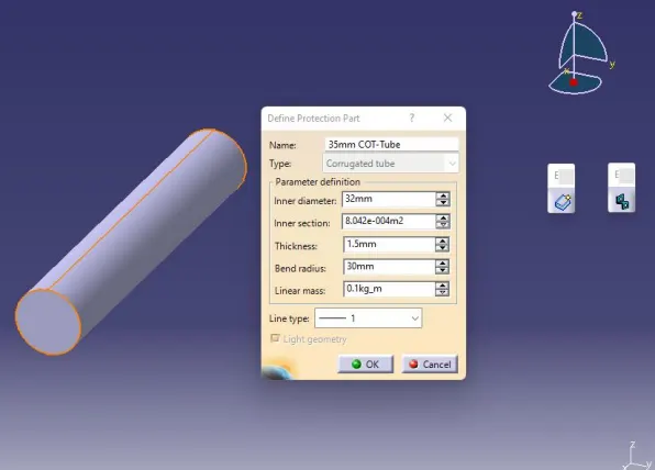
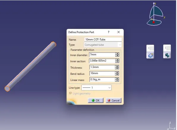
File ----> New Part ------> Switch to ‘Electric Part Design’ Workbench -------> Define Protection Part ------> Create the below COT Tubes
15mm COT-Tube
20mm COT-Tube
35mm COT-Tube
10mm COT-Tube
5mm COT-Tube
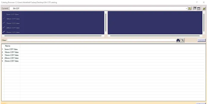
The corrugated tubes should be added to the catalogue under the "Slit COT" family. To make a new catalogue, click on “File”, then “New”, then “CatalogDocument”. After that, click on “Add Family”, as highlighted below.
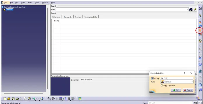
Include every corrugated tube in the catalogue that was already prepared.