Wiring harness routing & packaging Rules Week 3 Challenge
....
...
Week 3 Challenge
Wiring harness routing & packaging Rules
Aim:
The aim of the project is to study and understand the different models of the clips, back shell and corrugated tube and convert the given cad data file of the P clamp into electrical support and Backshell into the electrical back shell by electrical Part design workbench available in the CATIA V5 tool. Then create different corrugated tubes as per the given data and add them to a new catalog named “Slit COT”.
1. Design Preparation:
- Gather specifications: Collect all necessary information regarding connectors, P-clamps, harness length, routing paths, and any relevant design constraints.
- Review design guidelines: Adhere to industry standards and company-specific guidelines for wiring harness design.
2. Connector and P-Clamp Modeling:
- Create 3D models: Use CATIA V5's Part Design workbench to create accurate models of the connectors and P-clamps, ensuring proper dimensions and tolerances.
- Apply materials: Assign appropriate materials to the models for realistic physical properties and weight calculations.
3. Harness Path Definition:
- Utilize Wireframe and Assembly Design workbenches: Employ these workbenches to define the harness path, including bends, curves, and routing around obstacles.
- Consider constraints: Account for clearances, accessibility, and potential interferences with other components.
4. Harness Routing:
- Employ Generative Shape Design: Utilize this workbench to create the wire geometry along the defined path.
- Apply constraints: Maintain proper spacing and avoid sharp bends.
- Attach connectors: Position connectors accurately along the harness.
5. P-Clamp Placement:
- Position P-clamps: Place P-clamps at appropriate intervals to secure the harness.
- Ensure proper fit: Verify that the clamps hold the harness securely without damaging it.
6. Catalogue Creation:
- Generate product data: Create a catalogue with detailed information about the harness and its components, including
- Part numbers
- Dimensions
- Materials
- Installation instructions
- Maintenance guidelines
- Utilize Document Manager: Organize and manage catalogue data within CATIA V5's Document Manager.
Clips
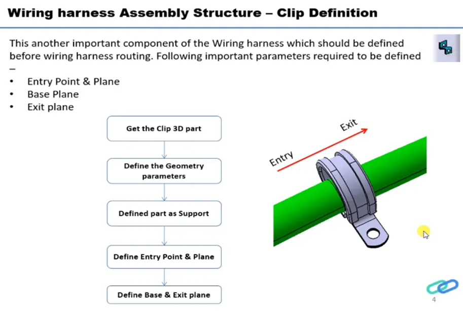
Clips are ideal elements for retaining / holding pipes, cables, cable harnesses, hoses etc. Clips act as form fitting adjustable bands for ease of assembly & installation. The band ends of the clips are reinforced to prevent any tearing or loosening due to high mechanical loads. ‘P’ clips are fitted with EPDM liners which help achieve a tighter grip on the cable / conduit & also act as dampeners for sound & vibration.
Back shells
A back shell is a mechanical device threaded into the rear of an electrical connector and is designed to provide screening, sealing, and reparability. Engineered to help resist corrosion and fit a wide range of circular connectors, back shell components help protect connections from mechanical wear, environmental conditions, and electromagnetic interference (EMI). These are available with and without screen termination, providing long-term, high performance in sealed and unsealed electronics systems.
Corrugated tubes
Corrugated tubes made from flame-retardant material these tubes will protect cables from impact and abrasion. They are highly flexible and have a high fatigue life, making them ideal for any installation. Depending on the intended use, corrugated tubing is manufactured in different diameters and from different materials. Even though these are usually rigid materials, convoluted plastic tubing becomes flexible and bendable due to its corrugated manufacturing method.
1) P clamp into electrical support
Steps followed
- Study the P-clamp clip model and understand how the cable / bundle is passed through it and identify the entry, exit, base and mechanically connected faces.
- P-clamp is a bidirectional clamp and we have to define the points and planes along three parameters, entry face, exit face and base face.
- Download the neutral data file (step file / igs file) of the p clamp from the given source and open it in the CATIA part workbench.
- Define the center points of entry and exit faces by selecting the appropriate edges and create the planes which is parallel through the points.
- We can create the base plane by directly offsetting it from the base face.
- Now switch to the electrical part design workbench and define the P-clamp model as an electrical support by using the define support part command.
- Repeat the same command for both entry/exit faces and by applying this the cad part model is converted into an electrical support model.
Q1. Download following clip cad data & define it as Electrical support using Electrical Part design Workbench. Define all the necessary properties.
Hellarmann Tyton – 21160129
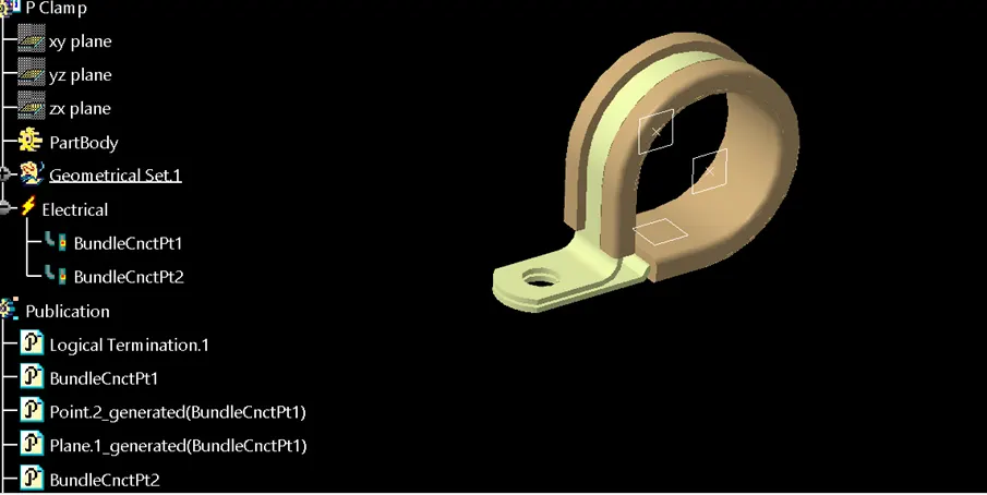
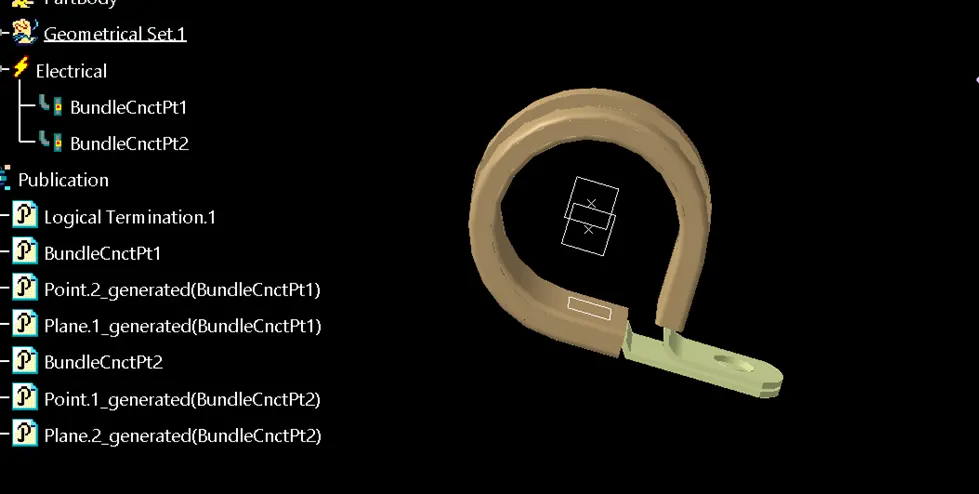
process:
- Create two points one as entry and another as exit point.
- create planes at two points and another at base.
- Switch to Electric part desgn
- Click on support defination - select part - select entry point - select entry plane, exit and base plane.
- Again Click on support defination - select part - select exit point - select exit plane and base plane as secondary plane is automatically taken.
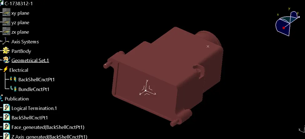
Q2. Download following Back shell cad data & define it as Electrical back shell using Electrical Part design Workbench. Define all the necessary properties.
Tyco 1738312-1 https://www.te.com/usa-en/product-1738312-1.html
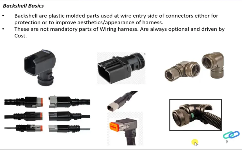
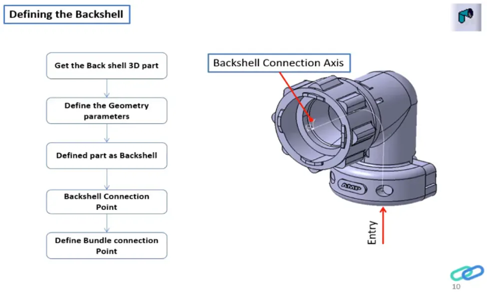
Process:
- create Back shell entry point.
- create axis system for back shell entry.
- create bundle connection point.
- switch to Electrical part design.
- Define part electricaly as back shell.
- Then define Back shell connection point.
- Define bundle connection point.
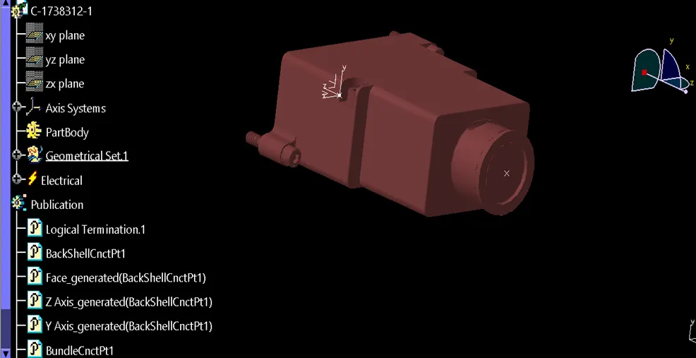
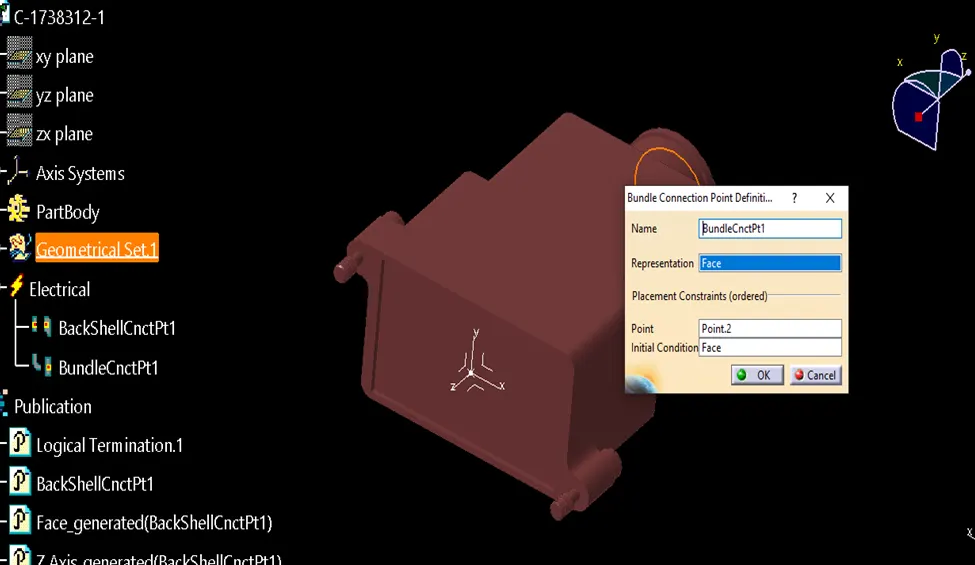
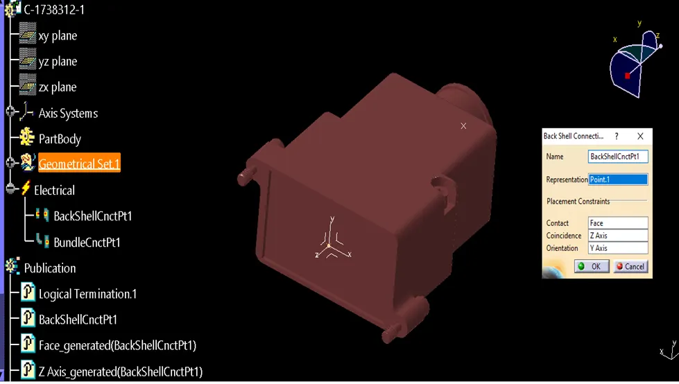
Q3. Create Following Corrugated tubes & Add them in Catalogue under “Slit COT” family.
|
Name |
ID (mm) |
OD (mm) |
Thickness (mm) |
|
15mm COT |
12 |
15 |
1.5 |
|
20mm COT |
17 |
20 |
1.5 |
|
35mm COT |
32 |
35 |
1.5 |
|
10mm COT |
7 |
10 |
1.5 |
|
5mm COT |
3 |
5 |
1 |
Process:
- Switch to Electrical part design
- Select Define protection Part
- Click on part (on file name in specification tree)
- Provide given parameters and bend radius as '1.5 x Outer Dia'.
Catalogue Cretation:
- new part - catalogue document - add family - give name - type - select Conduit - save.
- Open part to add catalogue - store device command - select catalogue - family - Slit_cot_tube - ok
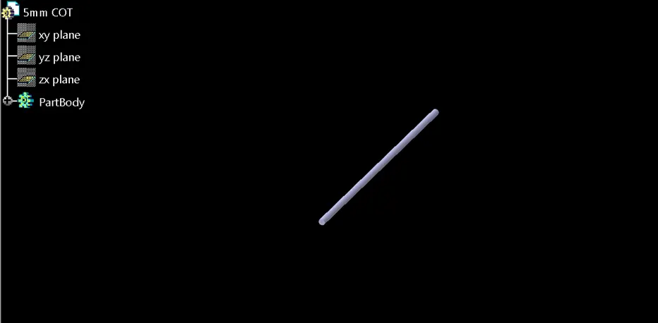
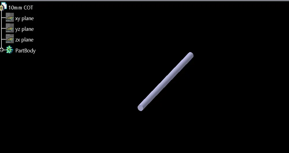
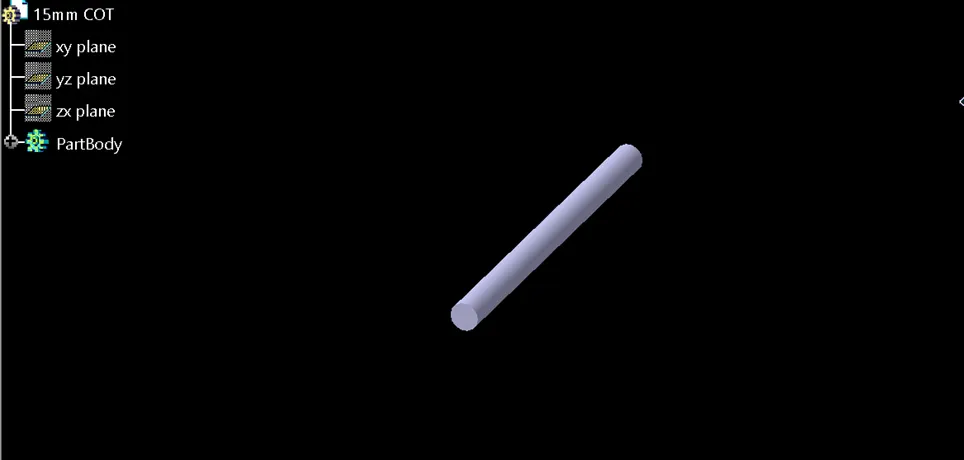
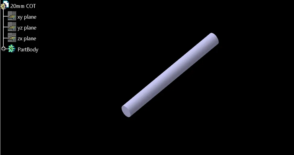
In electrical part design workbench and go to the define protection part command a pop-up window will appear to select the type as corrugated tube and give the appropriate inner diameter, thickness, bend radius as per the given input data and adjust the line type if required. Always keep a light geometry profile for protective coverings like corrugated tubes and insulation tapes.
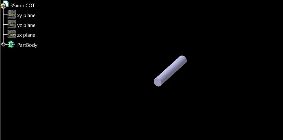
Saved corrugated tube files to catalog “Slit COT” using the command store device and by selecting the appropriate catalog and family.
Follow the same steps for creating different types of corrugated tubes and saved them to the catalog so that we can use them for further operations.
Conclusion
The cad part model the of P-clamp is converted into the electrical support model, back shell into the electrical back shell and create different corrugated tubes as per the given data and add them to a new catalog thereby understand the methods follow to create and convert the catalog, corrugated tubes, clips, back shells, and wiring harness routing and packaging rules.