Wiring harness routing & packaging Rules Week 3 Challenge
AIM - Downloading Back shell and P clamp cad data & define it as Electrical Connector using Electrical Part design Workbench. Define all the necessary properties.
HARNESS DESIGN PROCESS – Using Physical Architecture, Harness routing and packaging is designed.
STEP 1 - Identify the harness assembly components
STEP 2 - define all harness components as electrical
STEP 3 - prepare harness assembly
STEP 4 - define assembly as electrical assembly
STEP 5 – change tool setting as required
STEP 6 – start routing the bundles
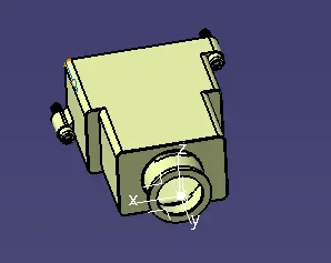
BACK SHELL –
STEP 1 – Create / download connector 3D
STEP 2 – Create required geometrical parameters
STEP 3 – Define part as Back shell
STEP 4 – Define back shell connection point
Geometry parameters – create a point on the face of the mating side and create a coordinate system at a point created with Y-AXIS should be pointing towards the front face of the connector, same direction as the harness to the connector, X-AXIS should be pointing in the direction towards the locking mechanism of the clip and Z-AXIS should be pointing across the connector from left to right. Can use your own but it should be consistent for mating connectors.
P CLAMP –
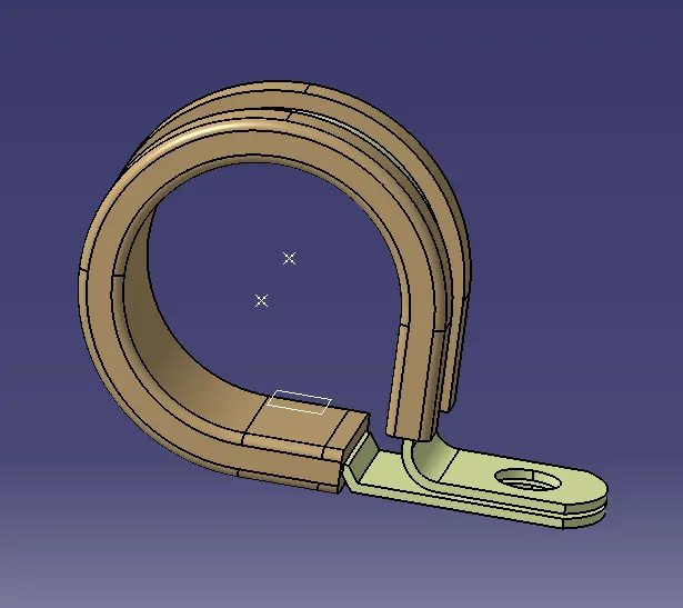
STEP 1 - Create a point on entry side and exit side of a clamp and plane on the wire enters and exits.
STEP 2 - Define part as Support part
We need to define two times as a support because wire can enters at two sides and exits at two sides.
CORRUGATED TUBES –
STEP 1 - Create Cot tubes of outer dia 5mm, 10mm, 15mm, 20mm and 35mm
STEP 2 - Create catalogue of cot tubes





COT 5 COT 10 COT 15 COT 20 COT 35