Wiring harness routing & packaging Rules Week 3 Challenge
Electrical support in wire harness refers to the various components, devices, and structures used to secure, protect, and manage the routing of electrical wires, cables, and connectors within a wiring assembly. The main purpose of electrical support is to ensure the wire harness's integrity, reliability, and functionality by preventing damage, minimizing interference, and maintaining proper organization of the components.
Clamp: A clamp is a mechanical device to secure and hold wires, cables, or other components within the harness. Clamps are designed to provide stability, prevent movement, and manage the arrangement of wires to ensure proper organization, protection, and reliability of the wire assembly
Objective:
- To create the wiring harness routing separately
- To create the wiring harness assembly of the Harness
- To add the annotations to the connectors.
Define the mechanical components electrically and prepare the catalogue for the connectors:
Step 1 – Downloaded the connector from the week 5 and week 6 challenges.
Step 2 – Geometrical parameters
Switch to part design
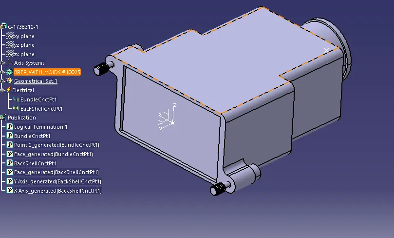
- Created point at bundle entry side and connector connection side.
- They created an axis system at the connector connection side.
- X-axis towards the locking mechanism
- Y–axis towards the front face of the connector
- Z–axis across the connector from top to bottom.
Step 3 – Define the part as a connector.
- Switch to electrical part design.
- Select the define connector command.
- Select the geometry.
- Type = single
- No of terminations = 4
Step 4 – Define bundle connection point.
- Switch to electrical part design.
- Select the bundle connection point command.
- Select the geometry.
- Name = We can rename it or keep the default.
- Representation – select the bundle entry face of the connector.
- Point – select the point that we created at the bundle entry side.
- Initial condition – select the bundle entry face of the connector.
Step 5 – Define the connector connection point.
- Switch to electrical part design.
- Select the connector connection point command.
- Select the geometry.
- Name – keep the default or rename it.
- Representation – Select the point that we created at the connector connection side.
- Contact – select the front face of the mating face of the connector.
- Coincidence – select y–axis.
- Orientation – select x–axis.
Catalogue:
Select file > new > catalogue document > add family > Name – connector > Type – Electrical.
Adding created part file into the catalogue:
- Open the Connector part file
- Switch to electrical part design.
- Select store device
- Catalogue – select the connector catalogue which is saved already in the device.
- Family – Connectors.
Create/Download Connector 3D:
Create a part using the Part Workbench.
Download CAD data from manufacturers' or distributors' official websites.
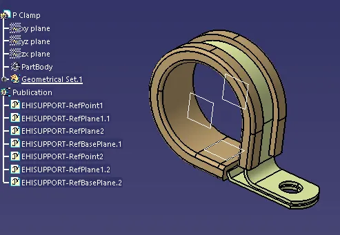
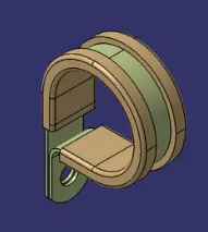
Conclusion:
CAD data is defined as Electrical support using an Electrical Part design Workbench and all the necessary properties are defined.
Bach Shell
A back shell, in the context of a wire harness or cable assembly, is a protective device that is used to cover and shield the connection point between a connector and a cable or wire bundle. It is often attached to the rear end (back) of a connector and provides several important functions like Strain Relief, Environmental Protection, Electromagnetic Interference (EMI) Shielding, Vibration and Shock Resistance, Cable Management and Ease of Termination.
CONNECTOR DEFINITIONS IN CATIA V5
The steps need to be followed to define the Back Shell using the Electrical Part Design Workbench.
Create/Download Connector 3D:
Download CAD data from manufacturers' or distributors' official websites.
- Create Required Geometrical Parameters:
- Create a Connection Point using the Part Workbench for Back Shell.
- Create the axis using point as reference using the Part Workbench.
- Create a Bundle Connection Point using the Part Workbench.
Corrugated tubes
Corrugated tubes, also known as corrugated conduits or corrugated hoses, are flexible cylindrical tubes with a corrugated (ridged) outer surface. They are commonly used in various industries, including electronics, automotive, aerospace, and industrial applications, to provide protection, insulation, and routing for cables, wires, and other components. Key features and uses of corrugated tubes include Cable and Wire Protection, Flexibility for Routing, Vibration and Impact Resistance, Easy Installation and Adaptability, Temperature and UV Resistance, Material Variety and Suitability, Electromagnetic Interference (EMI) Shielding, Diverse Types and Sizes, Color Options for Organization.
DEFINITIONS IN CATIA V5
The steps need to be followed to define the Back Shell using the Electrical Part Design Workbench.
Create 3D Part:
- Create a new part file and go to the Electrical Part Design Work Bench.
- Use the "Define Protection Part" option in the Electrical Device Definition Toolbar.
- Select the part file and define the protection part.
- Define the name, type, inner diameter, thickness and bend radius (Generally bend radius is 1.5 times the outer diameter) and click ok.
- The protection part (Corrugated tube/Tube) is created and saved the same in the catalogue
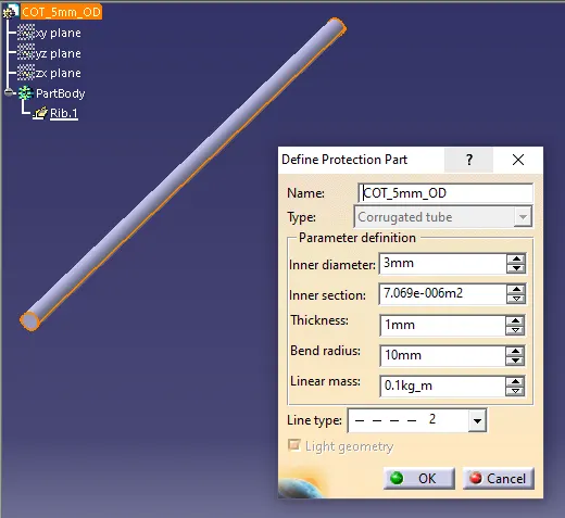
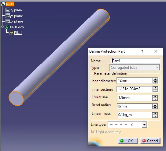
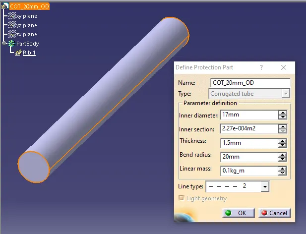
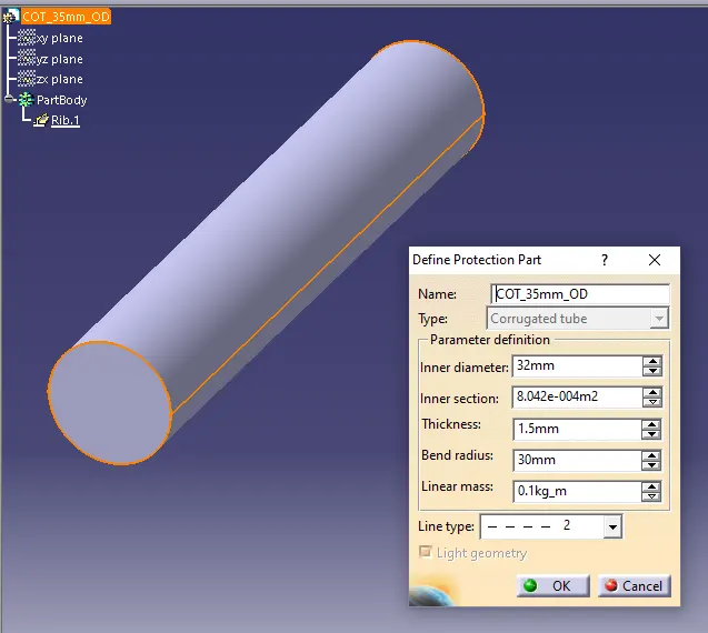
Conclusion: The corrugated tubes are created & Added to the Catalogue under the “Slit COT” family.