Wiring harness routing & packaging Rules Week 3 Challenge
Wiring harness routing & packaging Rules Week 3 Challenge.
Q1. Download following cad data & define it as Electrical support using Electrical Part design Workbench. Define all the necessary properties?
Ans) So as per given question i downloaded the cad data from te.com then open those cad part in catia v5 using the Part Design Workbench i define all geometrical properties as required and then define it as Electrical support using Electrical Part design Workbench. As below the image shown cad model.
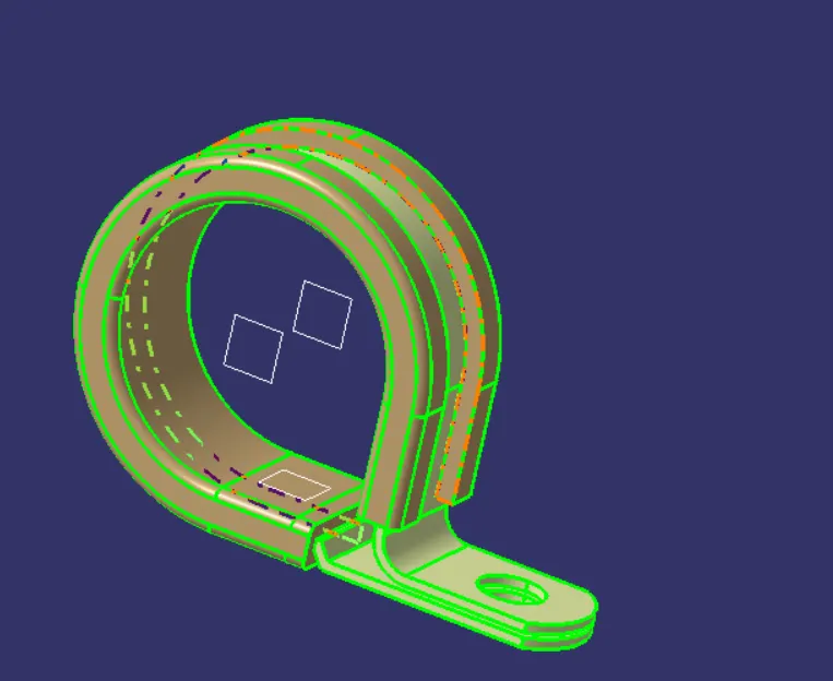
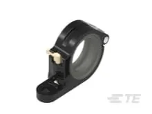
(Electrically define CAD part model of P-Clamp)
Introduction:
P clamps or p clips as they are also known are designed to assist in bundling and clamping applications for pipes, hoses and wires. Available in various materials and sizes, these screw mount clamps are stocked in a choice of different mounting hole and screw sizes dependant on your application and requirements.
P-Clamp enables next generation assembly, quick installation, and a flexible and ergonomic design. P-Clamp is the new solution for “tool-free” harness installation in military, aerospace, marine, and industrial applications.
Features:
QUICK
• Faster installation time than standard AS21919 P-Clamps
• Quick-lock feature allows operators to quickly open and close the clamp as needed
• Minimizes risk of FOD (Foreign Object Debris) with hardware free locking mechanism
FLEXIBLE
• Separate mounting and clamping features allow flexible and modular assembly processes
• Highly engineered PEEK material maintains strength without the weight
• 10 TE P-Clamp sizes cover the same range as 21 standard AS21919 P-Clamp sizes
• Weight savings opportunities compared to standard AS21919 P-Clamps
ERGONOMIC
• Tool-less lock and unlock feature enables quick and comfortable harness installation and rework
• Operator comfort leads to faster cycle times
Applications:
• Commercial Aviation
• Military Aerospace
• Military and Marine Vehicles
• Industrial Vehicles
• Rail
• Automotive
Q2. Download following Back shell cad data & define it as Electrical back shell using Electrical Part design Workbench. Define all the necessary properties?
Ans). So as per given question i downloaded the Back shell cad data from te.com then open those cad part in catia v5 using the Part Design Workbench i define all geometrical properties as required and then define it as Electrical back shell using Electrical Part design Workbench. As below the image shown cad model.
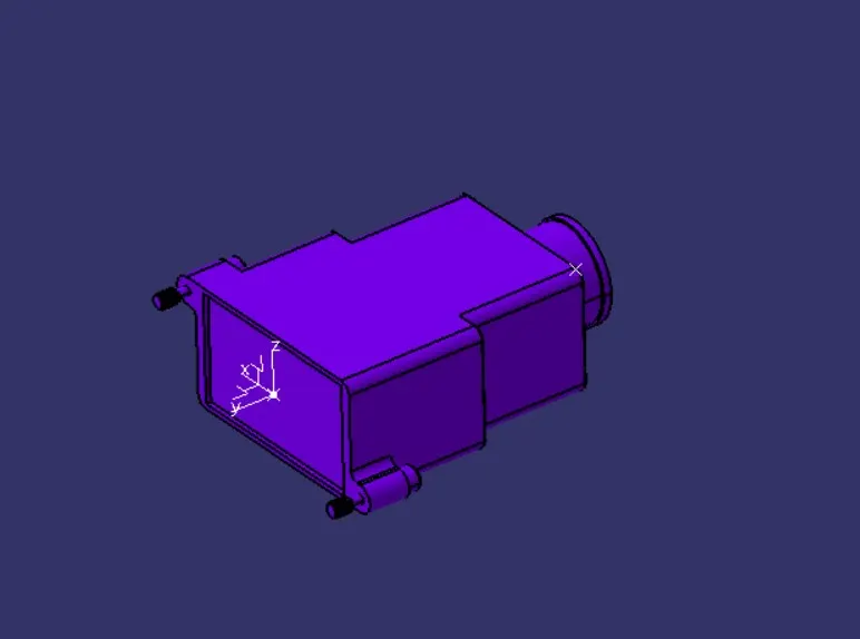
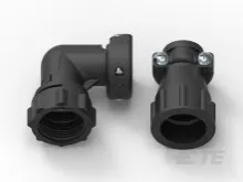
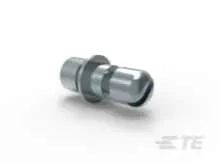
(Electrically define CAD part model of Back Shell)
Introduction:
Backshells are connector attachments that are designed to provide strain relief. They are commonly used with high-reliability connectors, such as military-specification (Mil-Spec) connectors. Backshells fit onto the back of connectors where they offer protection against strain-related damage.
Function/Working:
You might be wondering how backshells work exactly. While available in different types, they all work by forming a physical shell-like structure around the back of connectors.
Wires can still be exposed to various forces, including pulling forces. Backshells, though, protect connectors from damage caused by these forces. When fitted with a backshell, connectors will have a physical structure around the back where they connect to devices. The backshell will protect the enclosed connector from strain-related damage.
Type of Backshells:
All backshells consist of a shell-like structure, and they are all designed for use around the back of a connector. But there are many different types of backshells.
You can find backshells in different shapes. Many of them feature a cylindrical shape that wraps around the back of connectors. Other backshells feature an L-shaped design.
Backshells are available in different materials as well. Some of them are made of metal, such as aluminum. Alternatively, there are backshells made of synthetic materials like neoprene or rubber.
More than a strain relief:
While the primary purpose of backshells is to provide strain relief, they offer other benefits as well. Backshells can protect wires from environmental damage. High-quality backshells are often designed to withstand moisture as well as hot and cold temperatures.
Moisture can damage connectors. When exposed to moisture, the conductive surfaces within a connector may rust. Over time, this corrosion can cause them to fail. Backshells, though, are available to protect connectors from moisture and other forms of environmental damage.
Q3. Create Following Corrugated tubes & Add them in Catalogue under “Slit COT” family.
|
Name |
ID (mm) |
OD (mm) |
Thickness (mm) |
|
15mm COT |
12 |
15 |
1.5 |
|
20mm COT |
17 |
20 |
1.5 |
|
35mm COT |
32 |
35 |
1.5 |
|
10mm COT |
7 |
10 |
1.5 |
|
5mm COT |
3 |
5 |
1 |
Ans). I create the corruugated tubes by using the given data in electrical part design workbench by application of define protection part command. As below the image shown cad model.
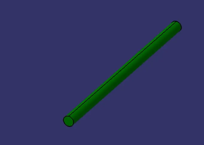
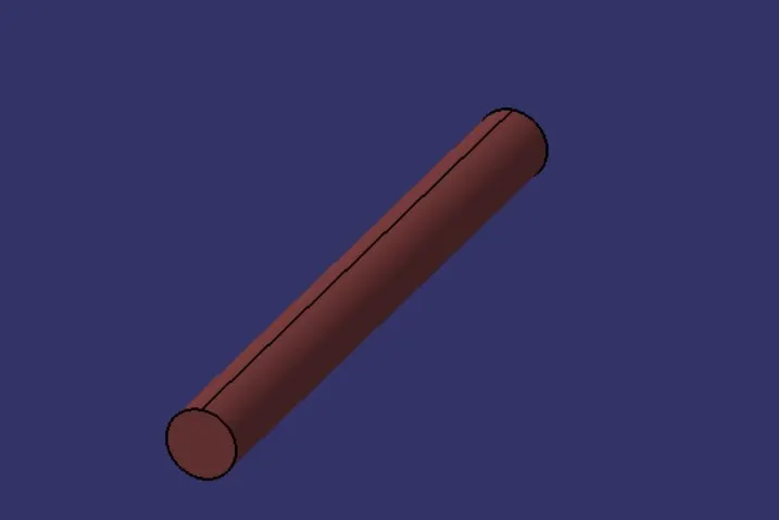
(Corrugated tube CAD models)
Defination:
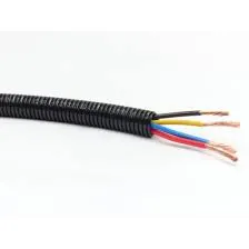
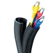
The cylindrical first regions of the corrugated tube are positioned adjacent to connectors at the ends of the wire harness. This feature allows electrical wires of the harness to be uniformly distributed therein and prevents them from being twisted when the electrical wires are inserted into cavities of the connectors.
A wire harness to be installed in a vehicle having a bundle of wires and a tube surrounding said bundle of wires, said tube being a corrugated tube having circumferentially extending corrugations along its entire length and along its length at least two first regions having a circular cross-section and between said first regions a second region having a first axis greater than the outer diameter of said cross-sections of said first regions and a second axis smaller than the outer diameter of said cross-sections of said first regions, wherein said second axis is transverse to said first axis.