Wiring harness routing & packaging Rules Week 3 Challenge
Wiring harness routing & packaging Rules Week 3 Challenge
A "wiring harness" is a bundled collection of electrical wires, cables, and connectors designed to transmit power and signals between different components in a system, while "routing" refers to the process of planning and physically arranging these wires within a device or vehicle to ensure proper functionality, safety, and efficient use of space, taking into account factors like heat management and potential interference; essentially, it's how the wiring harness is laid out and secured within a given area.
Routing process:
This involves determining the best path for the wires to follow within a system, considering factors like space constraints, component placement, and potential hazards.
Q1. Download following cad data & define it as Electrical support using Electrical Part design Workbench. Define all the necessary properties.
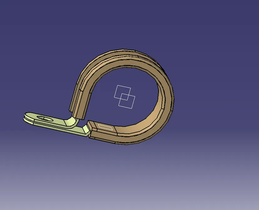
P Clamp
A P-clamp is used to hold a wiring harness in place along a vehicle's chassis, protecting it from wear and ensuring it stays organized.
Download the P clamp from the given link Provided .
Steps to follow :
Get the 3D part
Define the Geometry Parameters
Define Part as support
Define Entry and exit Plane with Base Plane.
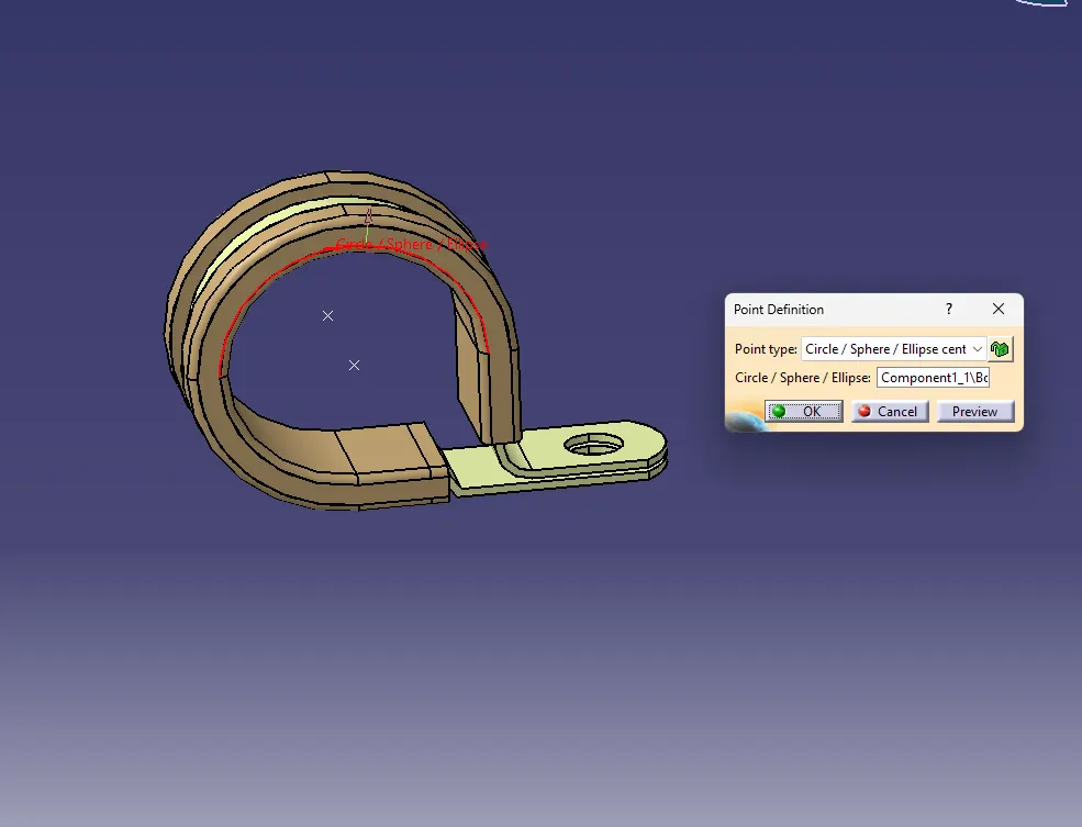
Create an Entry and Exit Point using point definition on both sides.
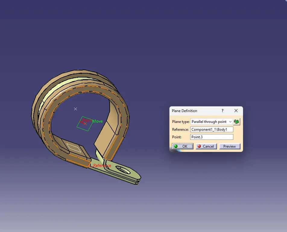
Create a Plane on the points created on both entry and exits where the cables or wire will be inserted and also create a base plane on the base of the clamp.
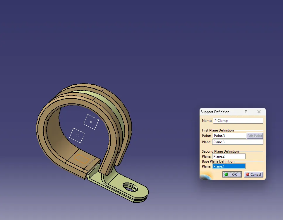
Define Support on both the entry and exit point of the clamp.
Once the support is created the pointer mark is not visible.
Q2. Download following Back shell cad data & define it as Electrical back shell using Electrical Part design Workbench. Define all the necessary properties.
Tyco 1738312-1 https://www.te.com/usa-en/product-1738312-1.html
Downloaded the 3D CAD file from the given link provided.
Steps to follow :
Get the 3D part
Define the Geometry Parameters
Define Part as Backshell
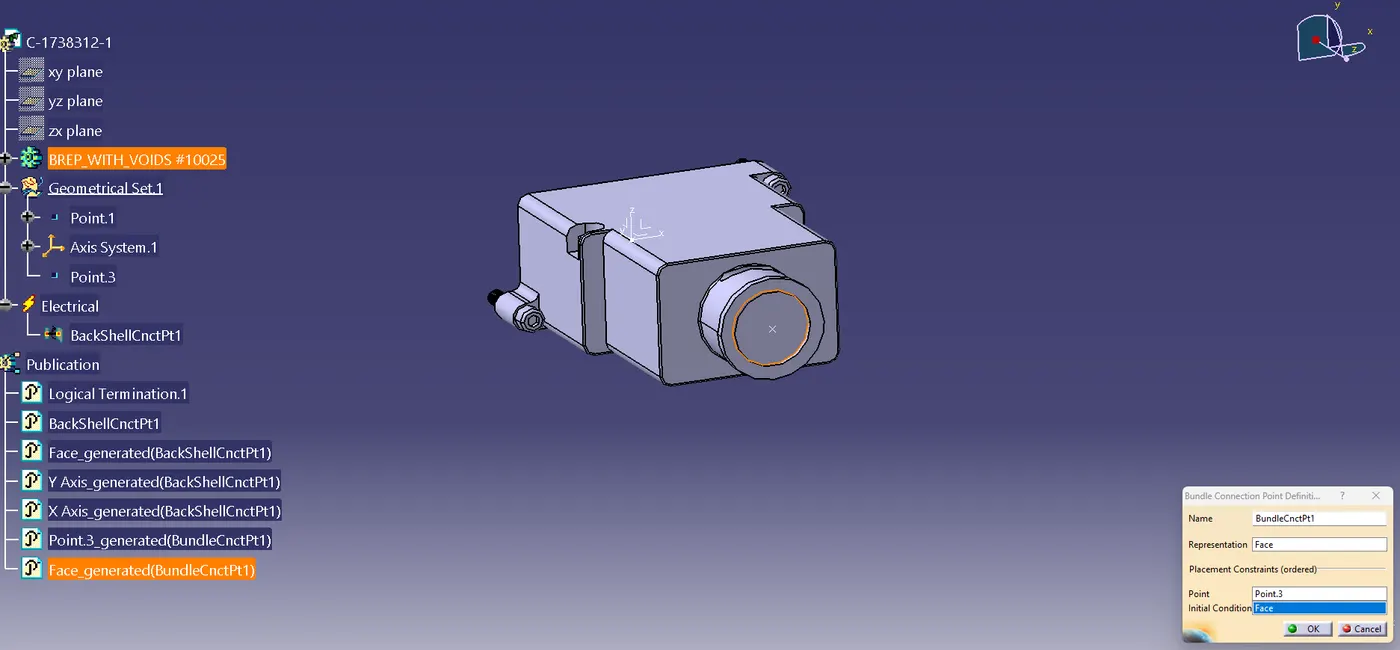
Define Backshell Connection Point.
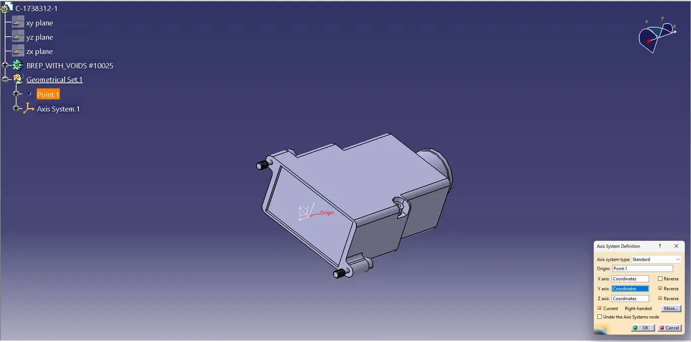
Point and Axis System is defined using Axis Definition System.
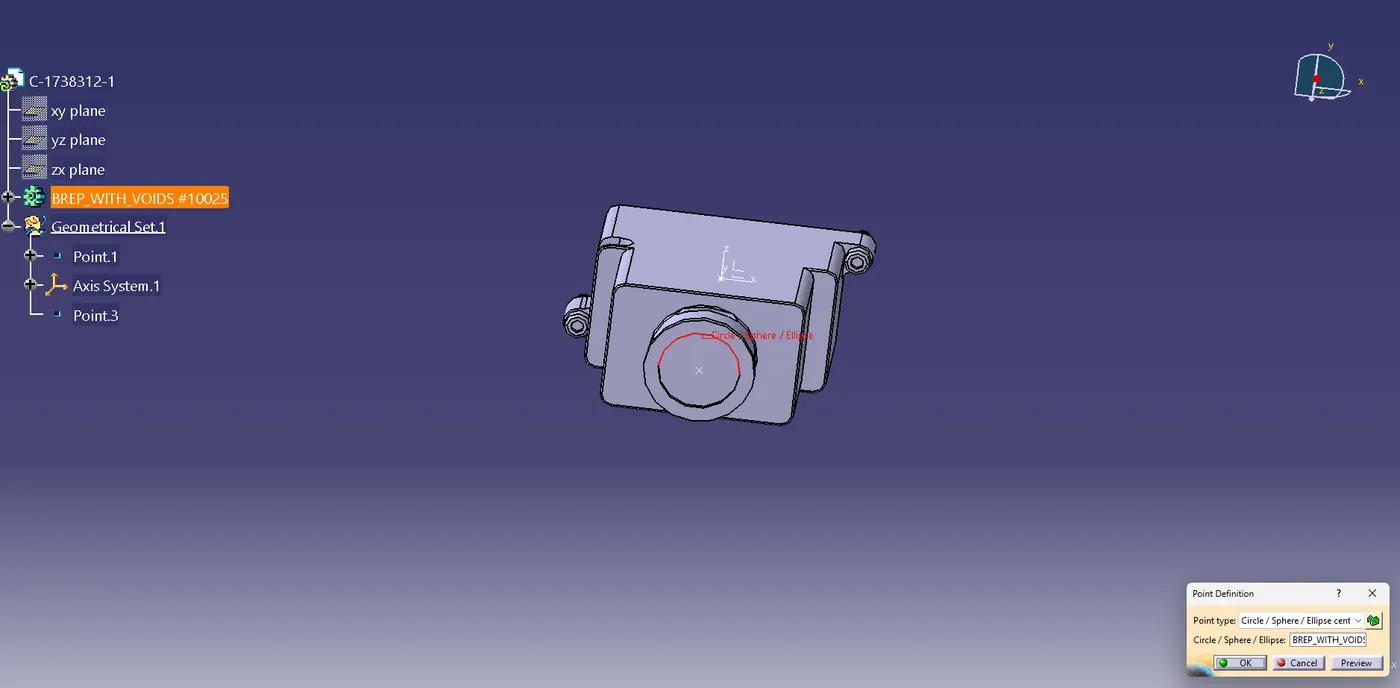
Backshell connection point is defined .
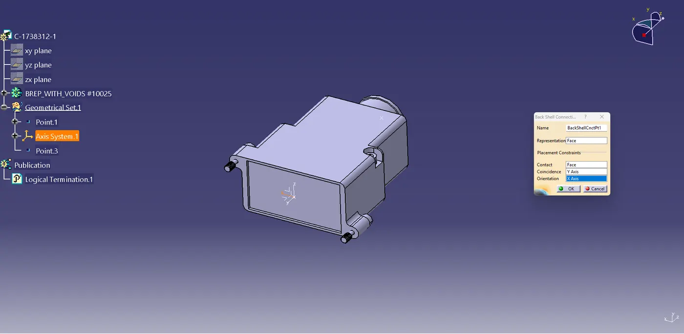
Bundle connection point is also defined on the other side of the part.
Q3. Create Following Corrugated tubes & Add them in Catalogue under “Slit COT” family.
Name | ID (mm) | OD (mm) | Thickness (mm) |
15mm COT | 12 | 15 | 1.5 |
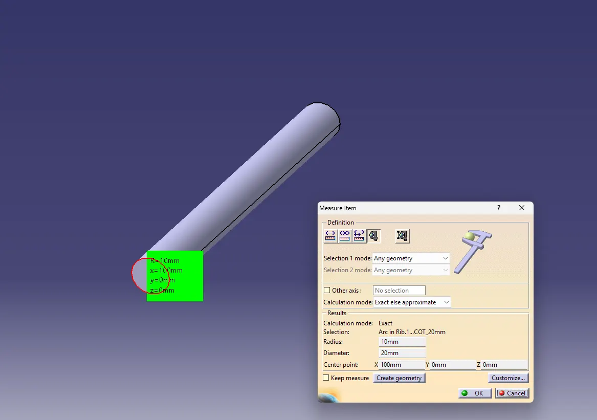
20mm COT | 17 | 20 | 1.5 |
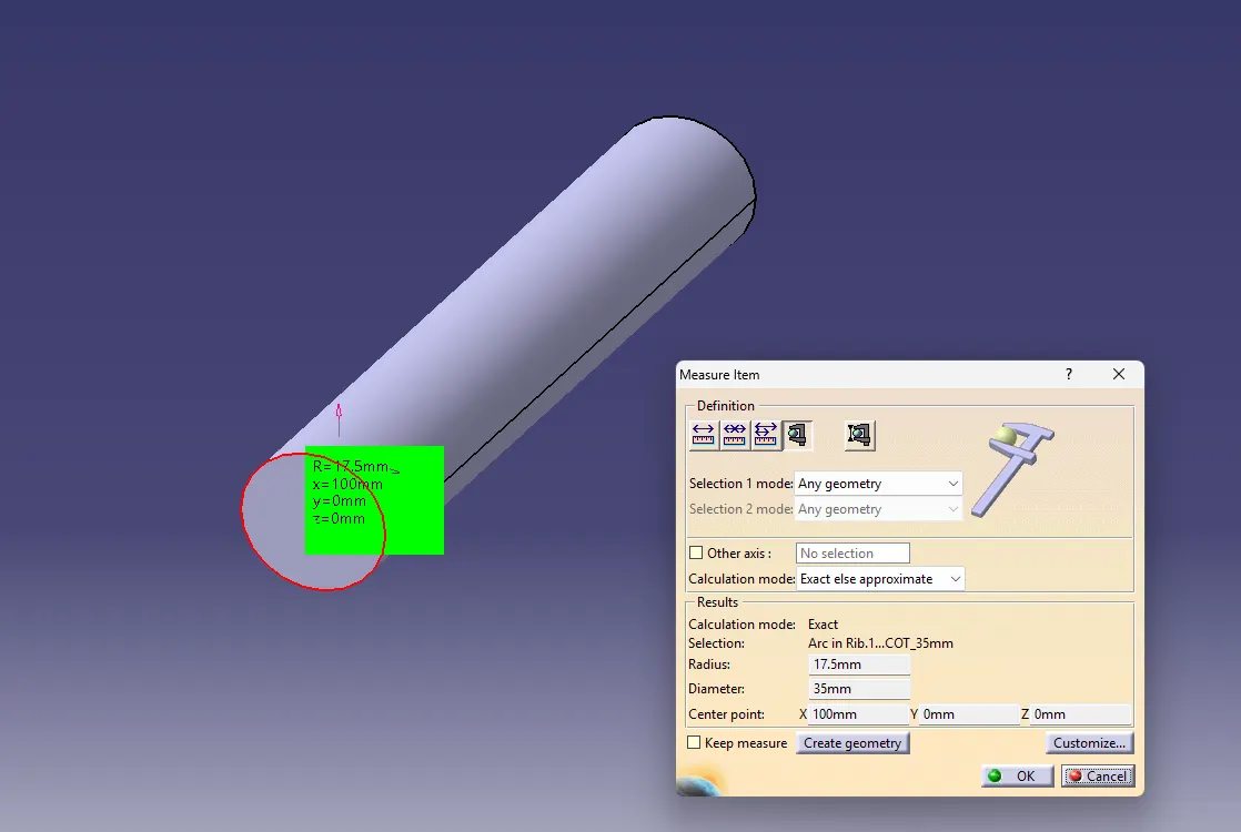
35mm COT | 32 | 35 | 1.5 |
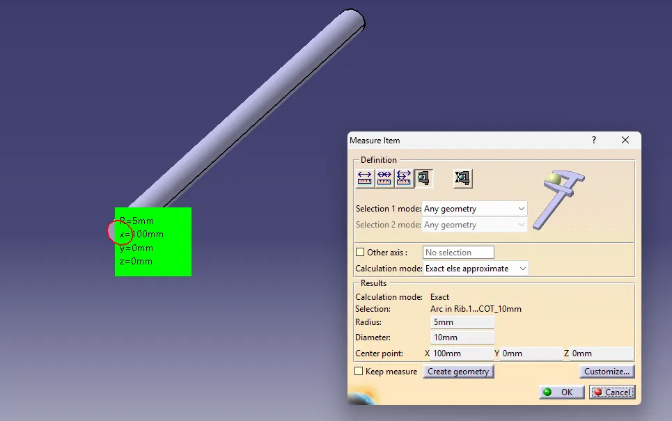
10mm COT | 7 | 10 | 1.5 |
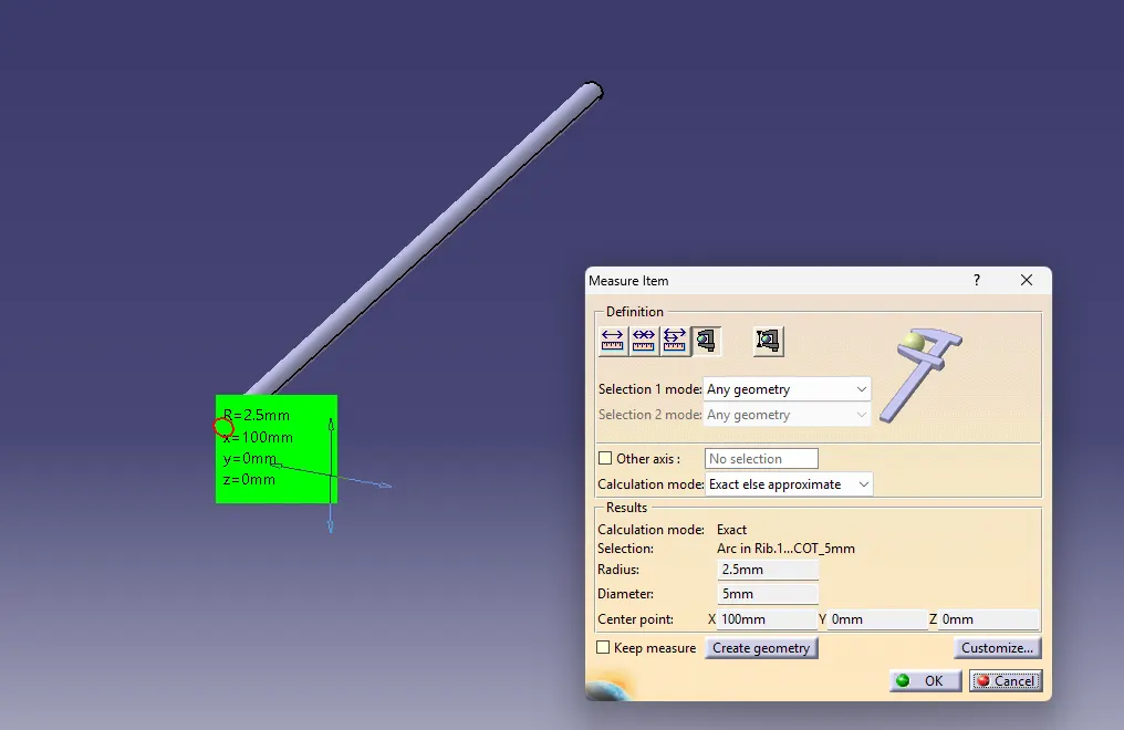
5mm COT | 3 | 5 | 1 |
Steps to follow:
Define Protection Part in Electrical Workbench
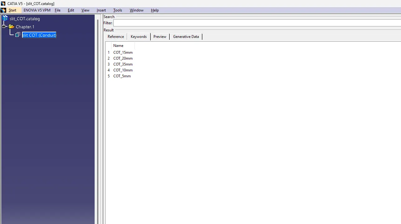
Create a catalogue with name and select type of conduit (in corrugated tubes conduit is used)
Save the Part
Store the Part in catalogue created .
These steps are followed in all the COT Tubes given.
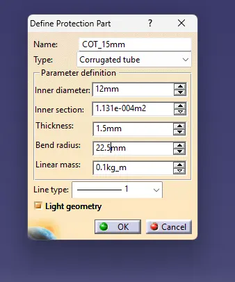
Protection Part is defined where Type is selected as Corrugated tube and the dimensions are taken as per the given data.
here one point to be noted that the bending radius is 1.5 times the outer radius.
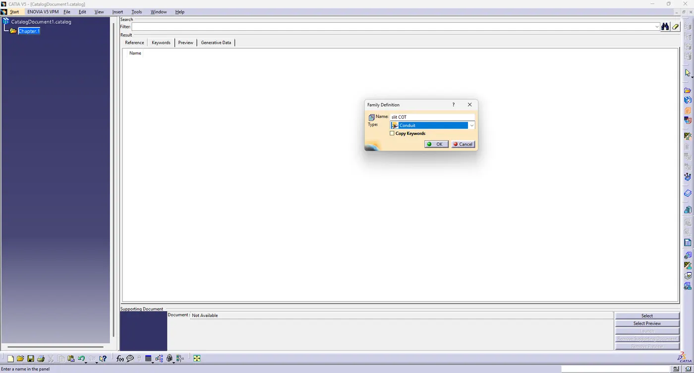
A catalogue is been created with the name of slit COT.
15mm COT
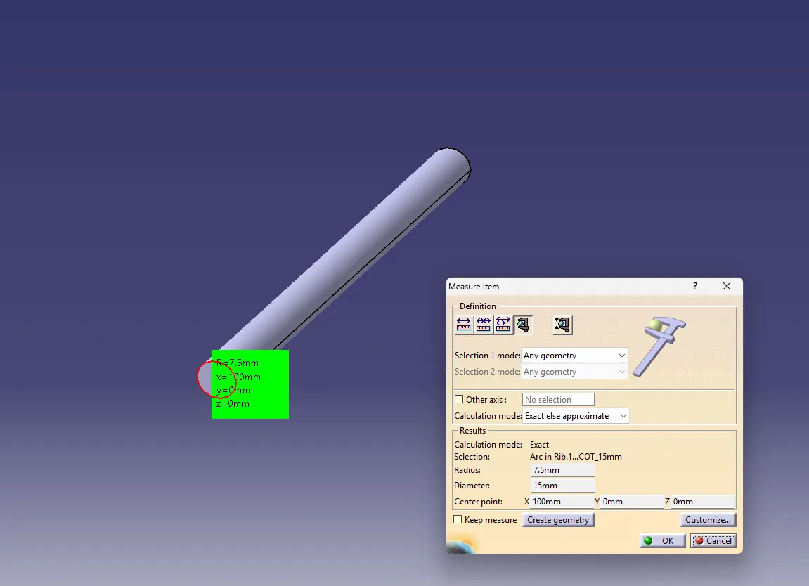
20mm COT
35mm COT
10mm COT
5mm COT
Catalogue Document