Wiring harness routing & packaging Rules Week 3 Challenge
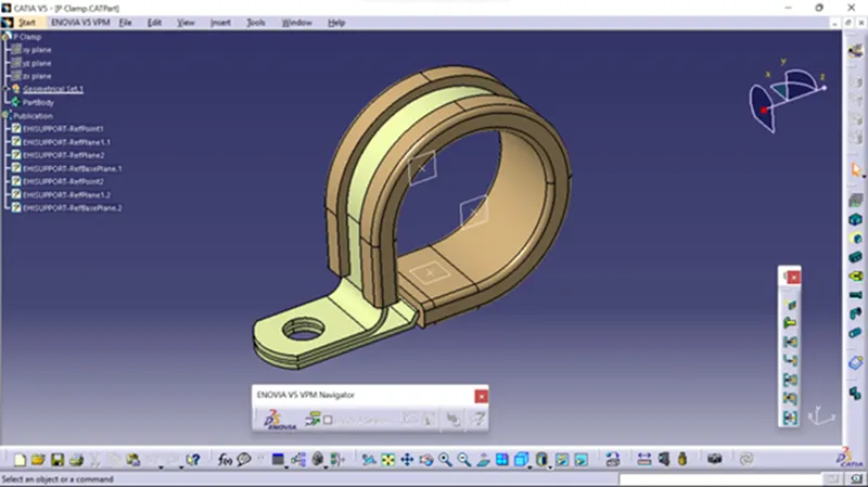
1. Download the following cad data & define it as Electrical support using Electrical Part design Workbench. Define all the necessary properties.
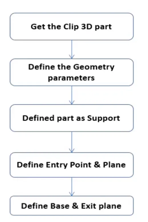
Steps.
- Once the File is Downloaded, Open the File Using CATIA V5
- Using the Part design model, we define entry, Exit, Base points, and Planes
- After determining the points and planes open the file in Electrical Part design
- Now we need to define the part as a Support using the Define support Part
- Here we use the Required points and planes as an Entry and exit of the clamp for one side
- And use the support definition again to give an entry point on the opposite side by selecting the point opposite of the first support definition while keeping the base plane the same
- (Note: if you face any issue with point definition, or point selection, Right-click on the point definition window and use the reset option.)
- After providing the necessary properties Save the file.
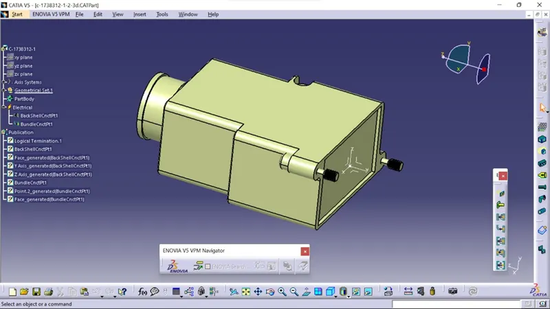
Q2. Download the following Back shell cad data & define it as Electrical back shell using Electrical Part design Workbench. Define all the necessary properties.
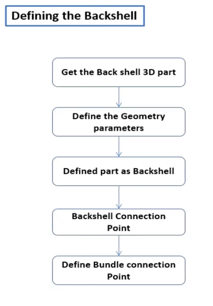
Steps.
- Once the File is Downloaded, Open the File Using CATIA V5
- Using the Part design model, we define 2 points as the Bundle entry and Connector connection point with Axis
- After determining the points and planes open the file in Electrical Part design
- Now we need to define the part as a Backshell using Define Back shell Feature
- After defining it as the Backshell we need to define the connection points
- End, where the Back shell is connected with the connector, is defined using Define Back Shell Connection Point Feature
- End where the bundle is connected to the back shell defined using Define Bundle Connection Point Feature
- After giving the necessary properties Save the file.
Tyco 1738312
Q3. Create the Following Corrugated tubes & Add them to the Catalogue under the “Slit COT” family.
|
Name |
ID (mm) |
OD (mm) |
Thickness (mm) |
|
15mm COT |
12 |
15 |
1.5 |
|
20mm COT |
17 |
20 |
1.5 |
|
35mm COT |
32 |
35 |
1.5 |
|
10mm COT |
7 |
10 |
1.5 |
|
5mm COT |
3 |
5 |
1 |
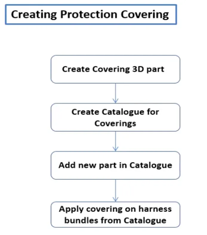
Steps.
- Open CATIA V5 with Electrical Part Design Model
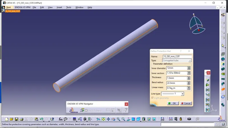
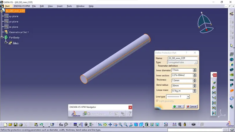
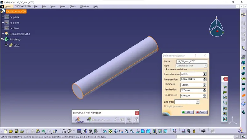
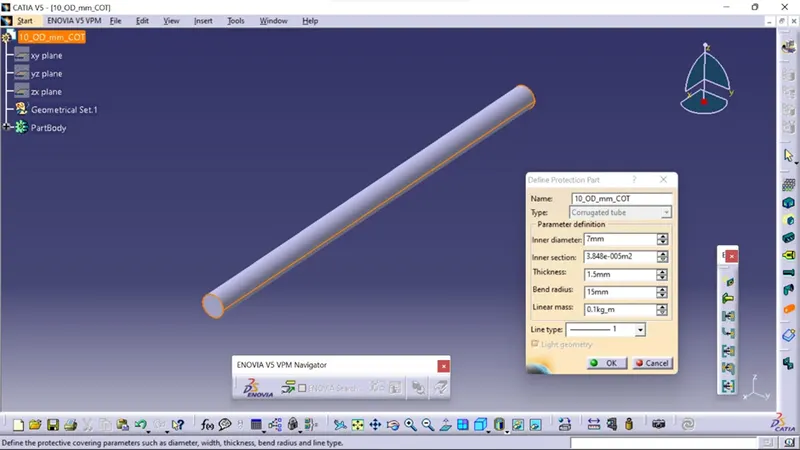
- Using Define Protection Part
- Select the type as Corrugated Tube
- Give the Required Parameters (Inner dia, Thickness, Bend Radii( Bend Radii= 1.5 times the OD))
- Click on OK
- After giving the necessary properties Save the file.
15mm COT
20mm COT
35mm COT
10mm COT
5mm COT