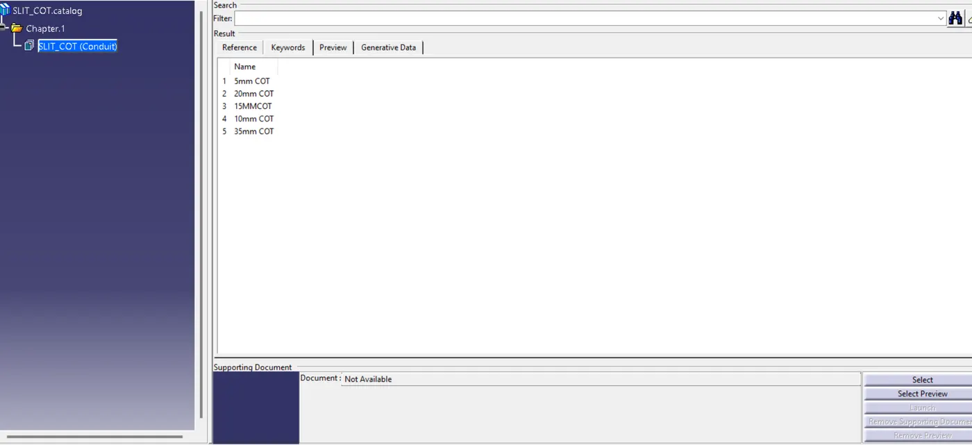
Wiring harness routing & packaging Rules Week 3 Challenge
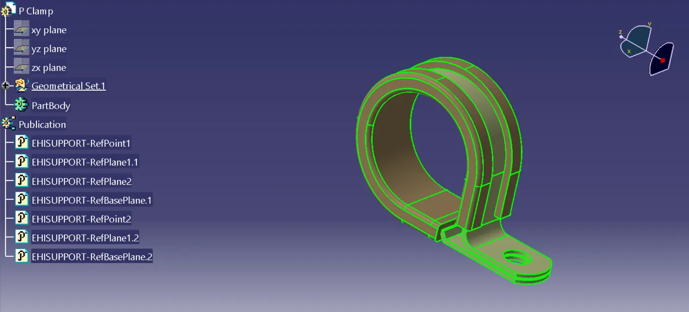
P CLAMP
1. Create or Import the P-Clamp Geometry
· Open the Part Design workbench.
· Model the P-Clamp geometry or import an existing design.
· Ensure it includes the following:
· A loop or semi-loop to hold the cable.
· A mounting feature, such as a hole or tab, for attachment to the structure.
2. Switch to the Electrical Part Design Workbench
Open the Electrical Part Design workbench:
Start > Equipment & Systems > Electrical Part Design.
3. Define the P-Clamp as a Support
Access the Support Definition Tool:
In the Electrical Part Design toolbar, select Define Support.
Assign the Bundle Clamping Area:
Click on the inner surface of the loop or semi-loop (the area that will hold the bundle).
Define the Support Type:
For a P-Clamp, select the option that allows the wiring bundle to pass through the loop while being secured.
Define the Mounting Point:
Use the Add Mounting Point tool to specify the hole or tab on the P-Clamp where it will be mounted.
Assign the Position and Orientation to align with the intended mounting surface.
4. Save the P-Clamp
Save the P-Clamp part with its defined electrical support attributes.
BACKSHELL
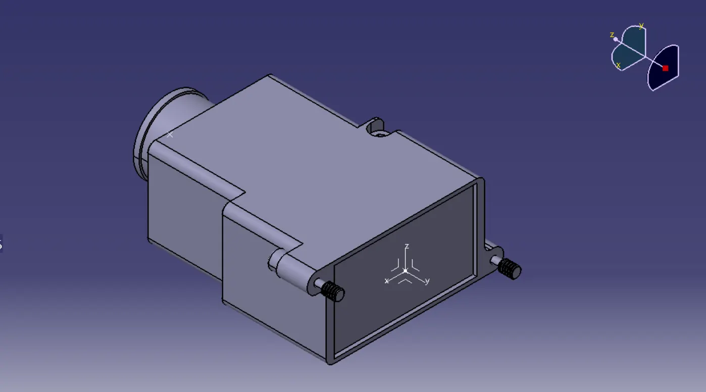
1. Create or Import the Backshell Geometry
1. Design the Backshell:
o Use the Part Design workbench to create the geometry of the backshell.
o Ensure it includes:
§ An opening for the connector interface.
§ A region for cable entry.
§ Any required mounting or locking features.
2. Import Existing Backshell Models:
o If you have a standard backshell model, import it into CATIA.
2. Switch to Electrical Part Design
- Open the Electrical Part Design workbench:
- Start > Equipment & Systems > Electrical Part Design.
3. Define the Backshell in Electrical Context
1. Access the Define Backshell Tool:
o In the Electrical Part Design workbench, select Define Backshell from the toolbar.
2. Select the Backshell Geometry:
o Click on the backshell part file to define it as an electrical component.
3. Define Connector Interface:
o Select the face or surface on the backshell that mates with the connector.
o This is typically the opening where the backshell attaches to the connector.
4. Define Bundle Entry Point:
o Select the face or surface where the cable or wiring bundle will enter the backshell.
o This ensures proper routing of cables through the backshell
4. Save the Defined Backshell
- Save the backshell part with its electrical definitions.
CATALOGUE CREATION
1. Prepare Connector Models
1. Design or Import Connectors:
o Create connectors in the Part Design workbench or import existing models.
o Define the connectors in the Electrical Part Design workbench:
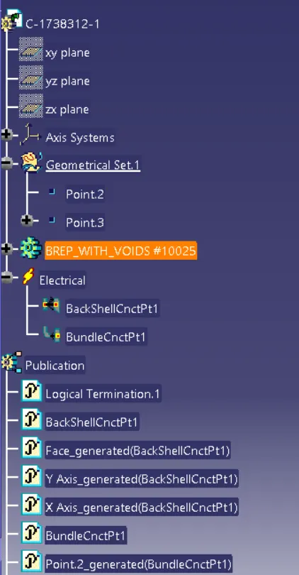
§ Assign connection points, cavity connection points, and bundle entry points.
§ Save the connectors with appropriate names for identification.
2. Organize Files:
o Place all connector files in a structured folder for easy reference.
2. Open the Catalog Editor
1. Access the Catalog Editor:
o Go to Start > Infrastructure > Catalog Editor.
2. Create a New Catalog:
o Click File > New to create a new catalog file.
o Save the catalog with a relevant name, such as ConnectorCatalog.catalog.
3. Define Chapters for the Catalog
1. Add Chapters:
o Right-click in the Catalog Editor and select Add Chapter.
2. Subdivide Chapters (Optional):
o For larger libraries, add sub-chapters to further categorize connectors by size, type, or manufacturer.
4. Add Components to the Catalog
1. Add Connector Parts:
o Right-click on a chapter and select Add Component.
o Browse to the location of the connector files and add them.
o Assign meaningful names and descriptions to each component for easy identification.
2. Define Attributes:
o Add custom attributes to each connector, such as:
§ Part Number
§ Connector Type
§ Voltage Rating
§ Material
§ Manufacturer
o Use the Define Attribute option in the Catalog Editor to create these fields.
5. Save the Catalog
- Save the catalog file after adding all connectors and attributes.