Wiring harness routing & packaging Rules Week 3 Challenge
WIRING HARNESS ROUTING & PACKAGING
AIM:
- Download following cad data (P CLAMP) then to define it as Electrical support using Electrical Part design Workbench and Define all the necessary properties.
- Download following Back shell cad data then to define it as Electrical back shell using Electrical Part design Workbench and Define all the necessary properties.
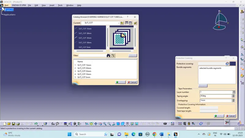
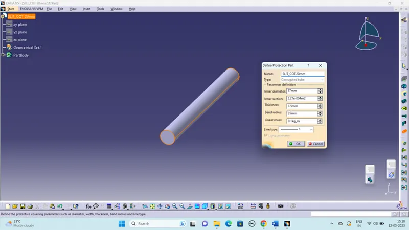
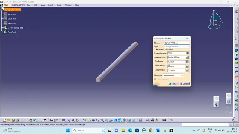
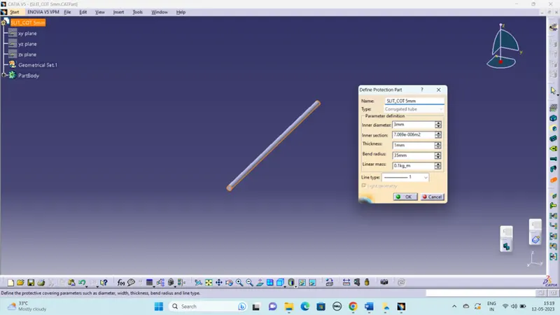
- To Create Corrugated tubes and Add them in Catalogue under “Slit COT” family.
CLAMP:
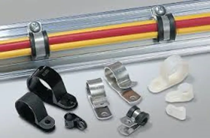
Cable clamps are cable routing clips or mechanical devices that help define the routing of cable and wire installations. These cable fasteners are designed to ensure retention and support to cables whilst restricting movement and will be found in almost every electrical installation.
STEPS TO FOLLOW:
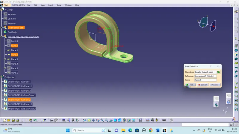
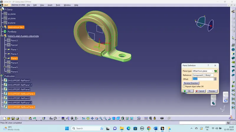
- The given clip was downloaded and opened as a part file.
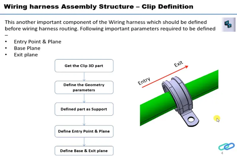
- I have to define two points that will be used as entry and exit points.
- Then a plane has to be defined at the points.
- A base plane has to be defined at a distance of 2 to 3 mm from the clip.
- Then define the entry point as well as plane, exit plane and base plane.
- Again define the exit point at the first definition as the entry point.
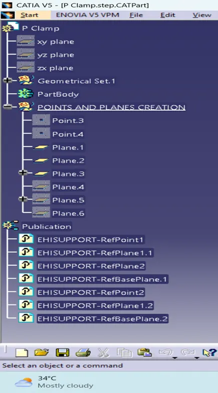
- The two entry and two exit points has been created.
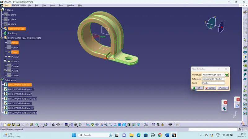
TREE STRUCTURE:
BACK SHELL:
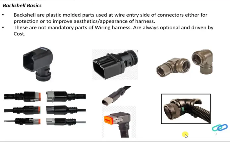
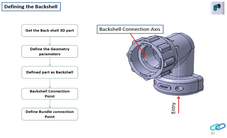
A back shell is a mechanical device threaded into the rear of an electrical connector. The more popular back shells are strain relief, cable clamps and adaptors.
GIVEN DATA:
Tyco 1738312-1 https://www.te.com/usa-en/product-1738312-1.html
STEPS TO FOLLOW:
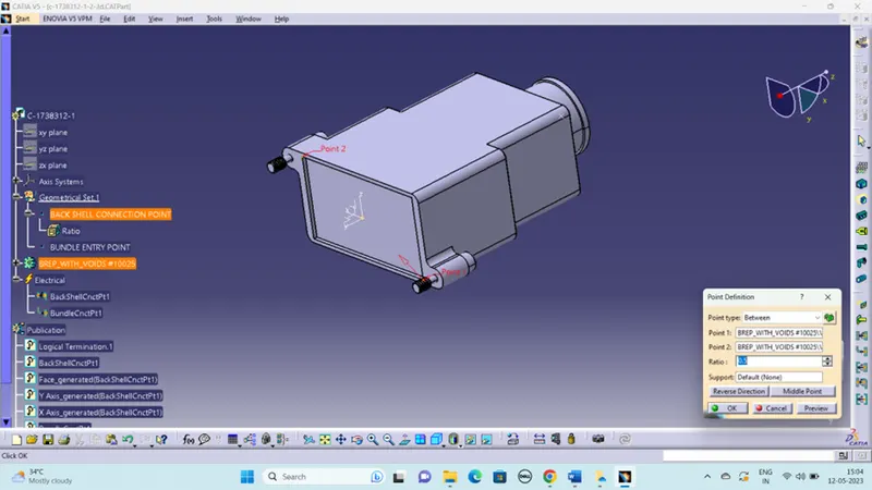
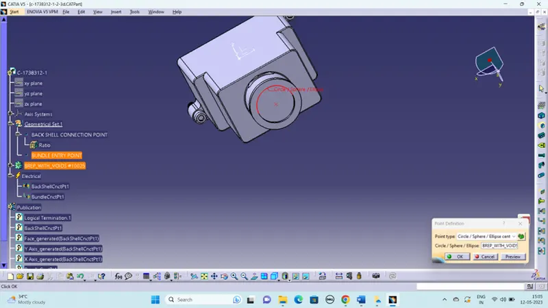
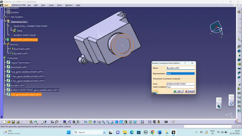
- create Back shell entry point.
- create axis system for back shell entry.
- create bundle connection point.
- switch to Electrical part design.
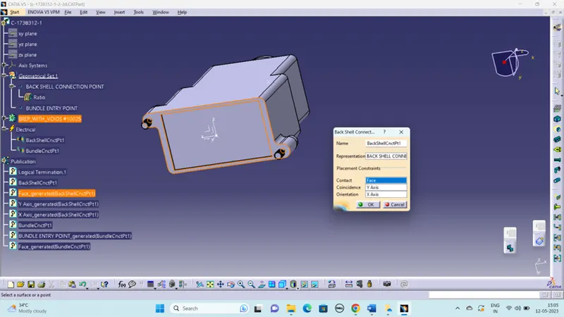
- Define part electrically as back shell.
- Then define Back shell connection point.
- Define bundle connection point.
CORRUGATED TUBES:
Corrugated tubing made out of plastics is now used in many fluid handling applications, though it has since developed many other uses, including as a conduit for electrical wiring or for transporting gases.
|
Name |
ID (mm) |
OD (mm) |
Thickness (mm) |
|
15mm COT |
12 |
15 |
1.5 |
|
20mm COT |
17 |
20 |
1.5 |
|
35mm COT |
32 |
35 |
1.5 |
|
10mm COT |
7 |
10 |
1.5 |
|
5mm COT |
3 |
5 |
1 |
STEPS TO FOLLOW:
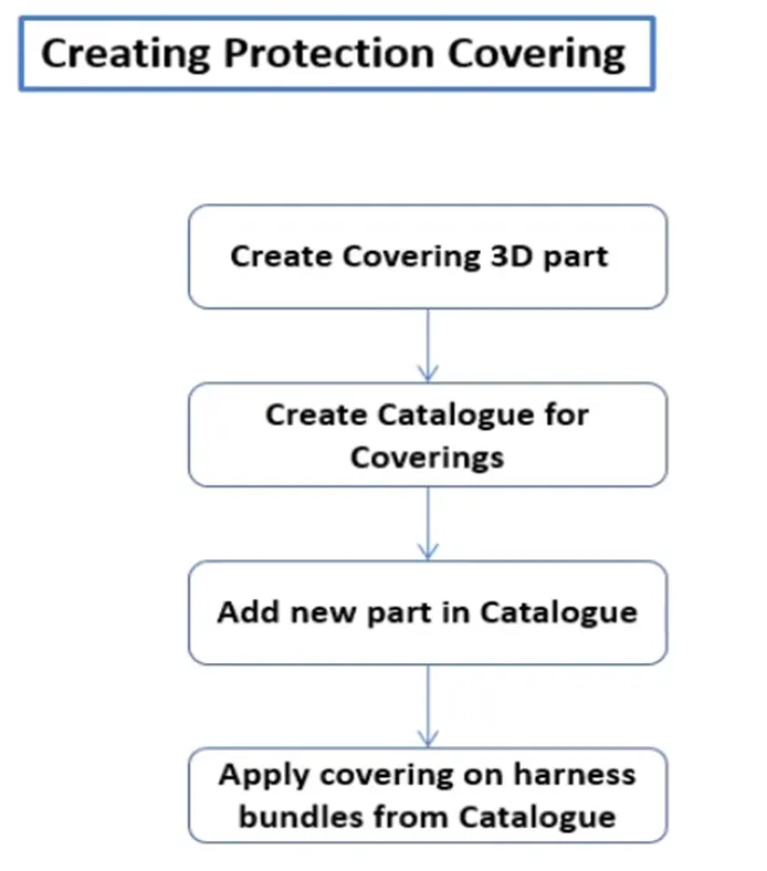
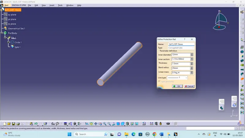
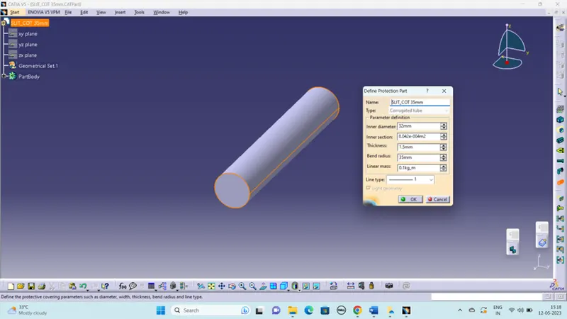
- Switch to Electrical part design
- Select Define protection Part
- Click on part (on file name in specification tree)
- Provide given parameters inner diameter and bend radius(35mm).
CATALOGUE CREATION:
- new part - catalogue document - add family - give name - type - select Conduit - save.
- Open part to add catalogue - store device command - select catalogue - family – SLIT_COT – ok
CATALOGUE: