Wiring harness routing & packaging Rules Week 3 Challenge
Objective -1
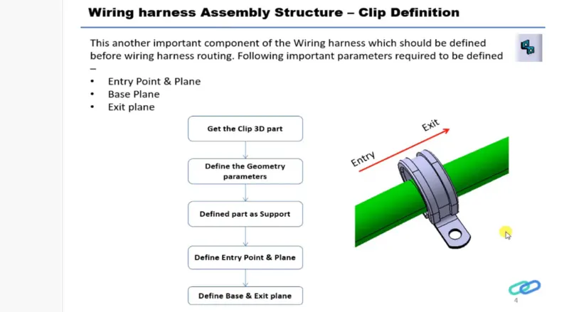
-Download following cad data & define it as Electrical support using Electrical Part design Workbench. Define all the necessary properties For P Clamp
Process -
step -1
Download the P clamp
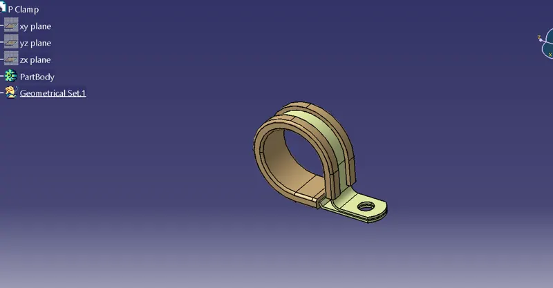
Step -2 Define geometric parameters
Create two points one as Entry and another Exit point
Create planes at two points and another at base
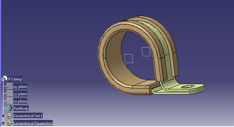
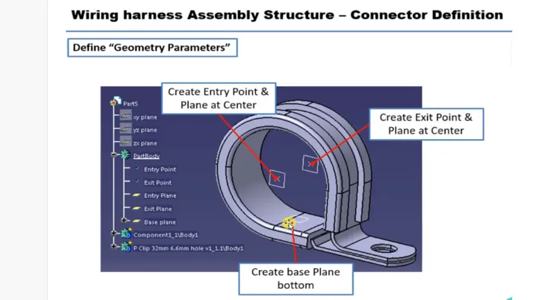
Switch to Electric part design
Click on support definition-select part- select Entry point-select entry plane, exit and base plane
Again click on support definition- select part -select exit point -select exit plane as secondary plane is automatically taken
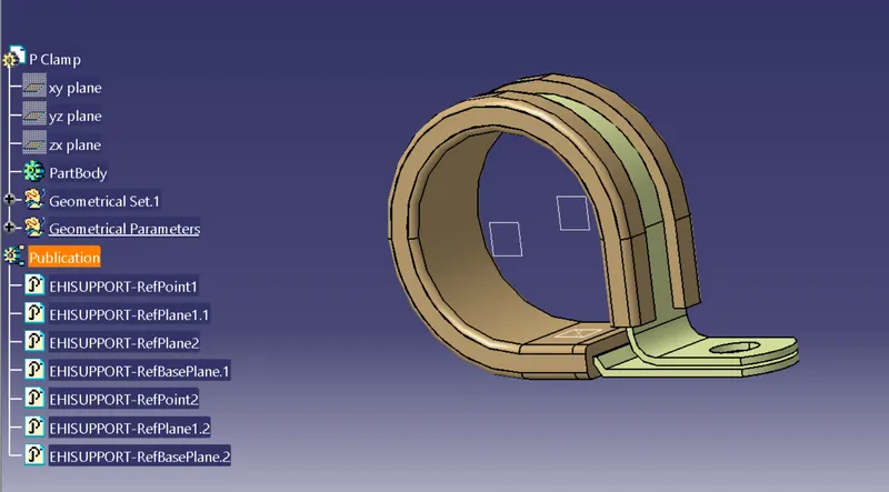
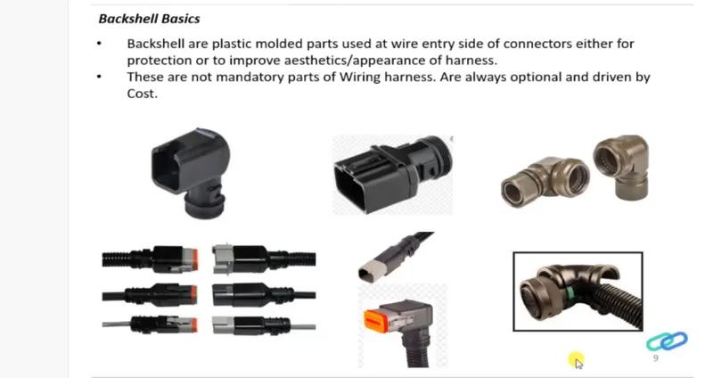
Objective -2 Download following Back shell cad data & define it as Electrical back shell using Electrical Part design Workbench. Define all the necessary properties for Back Shell
Tyco 1738312-1 https://www.te.com/usa-en/product-1738312-1.html
Process-
step -1
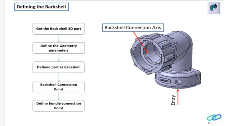
Download the back shell
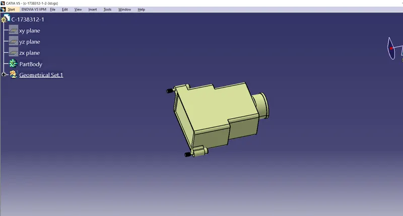
Step -2 Define geometric parameters
Create Back shell entry point
Create axis system for back shell entry
Create bundle connection point
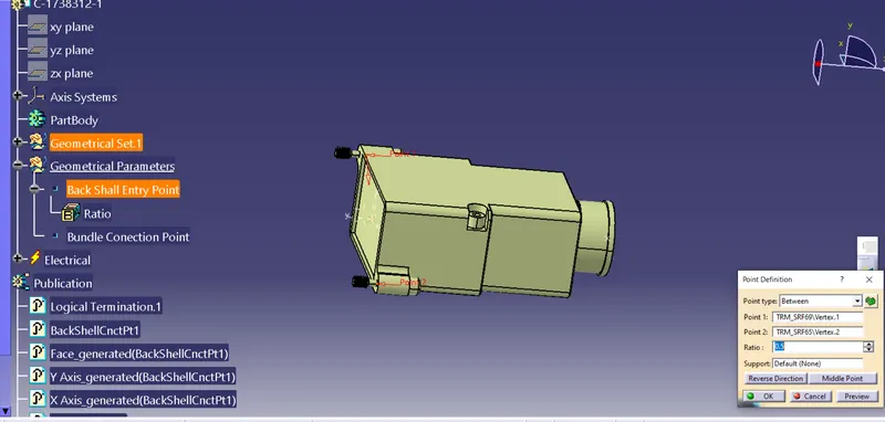
Switch to Electrical part design
Define part electrically as back shell
Then define Back shell connection point
Define bundle connection pont
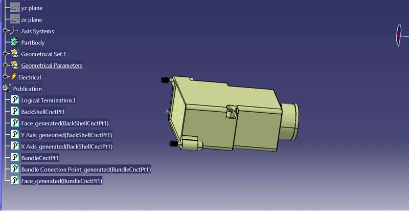
Objective -3
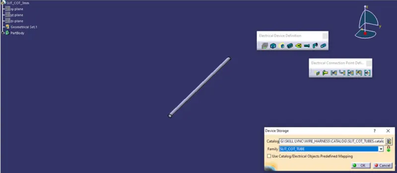
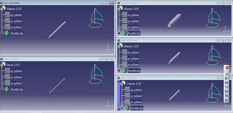
Create Following Corrugated tubes & Add them in Catalogue under “Slit COT” family.
|
Name |
ID (mm) |
OD (mm) |
Thickness (mm) |
|
15mm COT |
12 |
15 |
1.5 |
|
20mm COT |
17 |
20 |
1.5 |
|
35mm COT |
32 |
35 |
1.5 |
|
10mm COT |
7 |
10 |
1.5 |
|
5mm COT |
3 |
5 |
1 |
Process-
Switch to Electrical part design work bench.
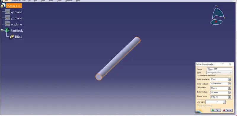
Select define protection part
Click on part (on file name in specification tree)
Give values for inner Diameter,Thickness and Bend radius 1.5 times of outer diameter