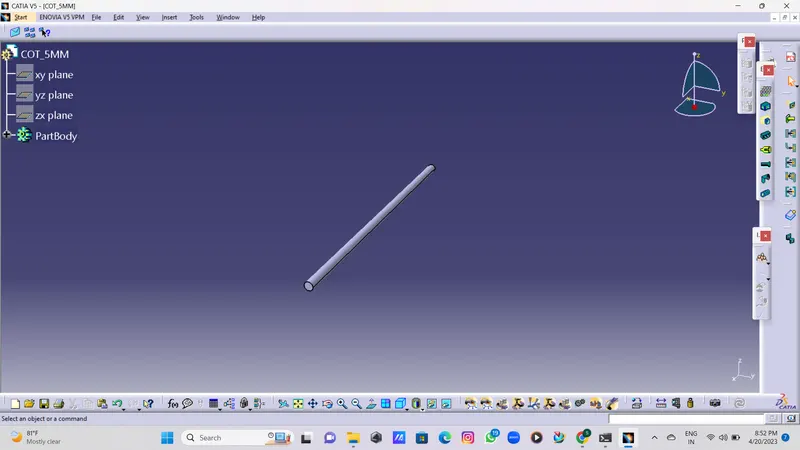
Wiring harness routing & packaging Rules Week 3 Challenge
Q1. Download the following cad data & define it as Electrical support using Electrical Part design Workbench. Define all the necessary properties.
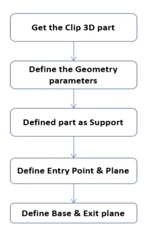
*Steps.
-
1. After downloading the file, open it in CATIA V5.
2. We specify entry, exit, base points, and planes using the Part Design Model.
3. Open the file in Electrical Part design after finding the points and planes.
4.Use the Define support Part command to define the part as a support.
5. In this case, the clamp is entered and exited using the necessary points and planes on one side.
6. Then, while maintaining the same base plane, use the support definition once more to provide an entry point on the opposite side by choosing the location across from the first support definition.Having provided the required properties File saving.
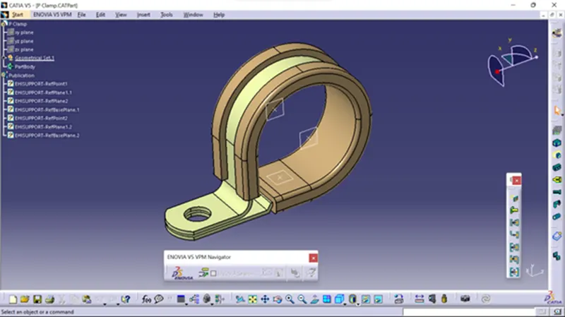
Q2. Download the following Back shell cad data & define it as Electrical back shell using Electrical Part design Workbench. Define all the necessary properties.
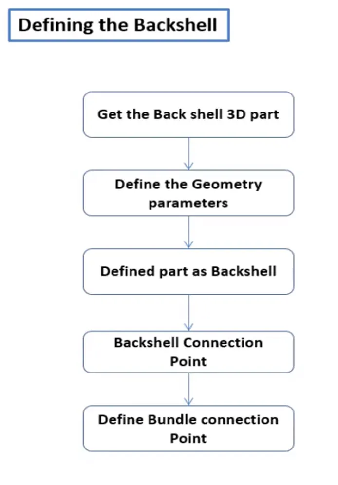
Steps.
1. After downloading the file, open it in CATIA V5.
2. We define 2 points as the Bundle entry and Connector connection point with Axis using the Part design model.
3. Open the file in Electrical Part design after finding the points and planes.
4.Use Define Back shell Feature to define the part as a Backshell.
5. Once the Backshell has been established, the connection points must be established.
6. Using the describe Back Shell Connection Point Feature, describe the end where the Back shell is attached to the connector.
7.End defined by the Define Bundle Connection Point Feature where the bundle is attached to the back shell.
8. Following the requisite qualities, File saving.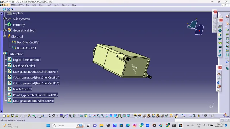
-
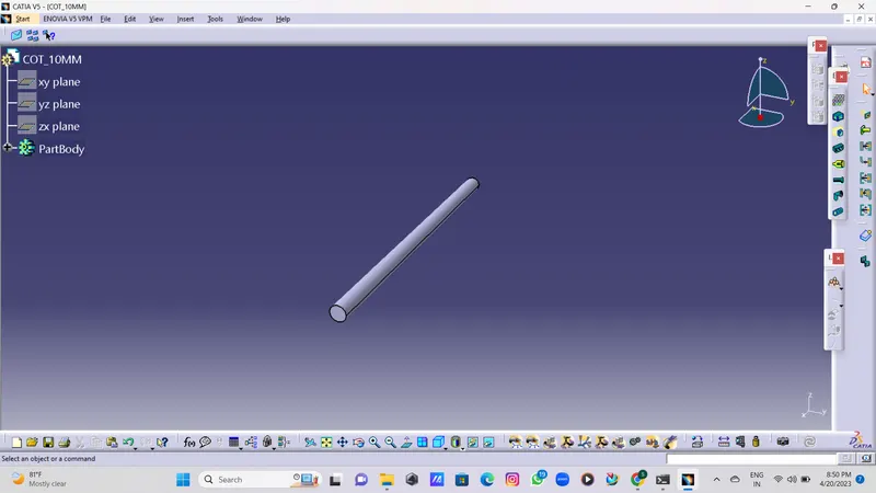
Q3. Create Following Corrugated tubes & Add them in Catalogue under “Slit COT” family.
*15MM COTName
ID (mm)
OD (mm)
Thickness (mm)
15mm COT
12
15
1.5
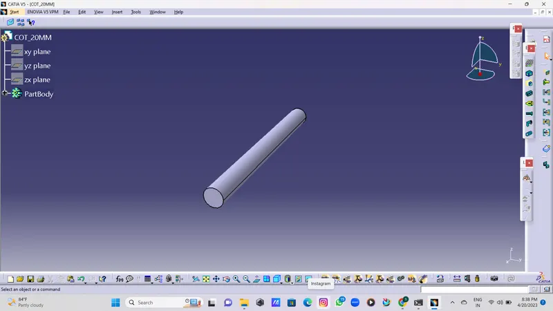
20mm COT
17
20
1.5
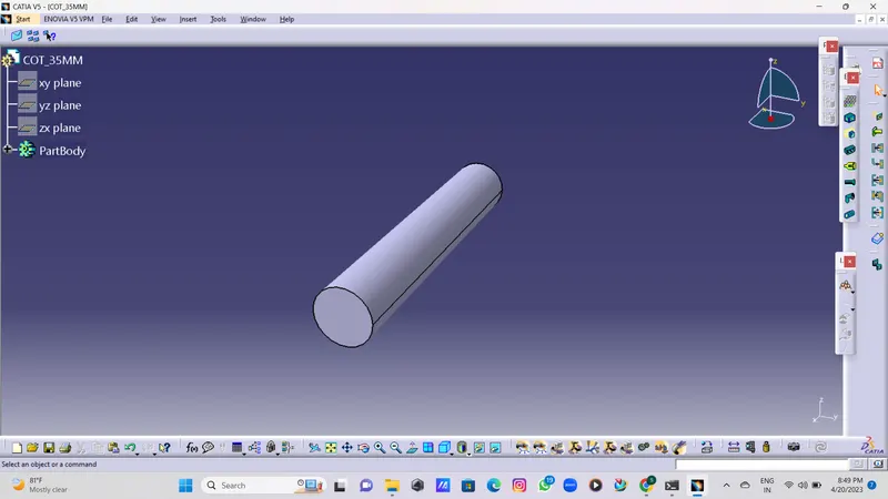
35mm COT
32
35
1.5
10mm COT
7
10
1.5
5mm COT
3
5
1
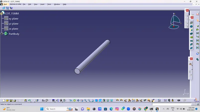
- *20MM COT
- *35MM COT
- *10MM COT
- *5MM COT